

To find out the cost of the cable, send the order code to our managers.
Delivery is carried out as soon as possible after the order is placed.
Symmetric communication cables of the U/UTP, F/UTP brands are designed for use in structured cabling systems for signal transmission in the frequency range up to 1000 MHz at an operating voltage not exceeding 145 V AC with a frequency of 50 Hz.
The cables can be used both for single installation in cable structures and industrial premises, as well as for group installation in areas of permanent personnel presence.
Cable construction
The conductors are single-wire or multi-wire, made of soft copper or tinned copper wire.
* By agreement with the customer, cables with a different number of pairs or quads may be manufactured.
| Cable brand | Nominal number of pairs, quads |
| U/UTP, F/UTP, U/UTQ, F/UTQ, U/FTP, F/FTP, U/FTQ, F/FTQ | 1, 2, 4, 10, 16, 25 |
The insulation of the conductors is made of solid polyethylene in the form of a concentric layer, hermetic, and free of foreign inclusions.
By agreement with the customer, the AWG (American Wire Gauge System) value may be specified in the cable designation.
| AWG value | Conductor diameter of the cable, mm |
| 22 | 0.64 |
| 23 | 0.57 |
| 24 | 0.52 |
Core
In twisted pair cables, two insulated conductors (“a” and “b”) of different colors are twisted into a pair. In quad-twist cables, four insulated conductors (“a”, “b”, “c”, “d”) of different colors are twisted into a star quad with unidirectional twisting. In a quad, two conductors positioned diagonally (“a” and “b”) and (“c” and “d”) form a working pair.
It is allowed to apply the color of the insulation of conductor “b” to the insulation of conductor “a” in the form of a longitudinal solid or dashed stripe (one or more), or in the form of ring (transverse) stripes at a distance of 35 cm.
The twist pitch ranges from 8 to 25 mm. The twist pitches of each pair (quad) are different and non-multiple.
| Pair number in the elementary or 25-pair bundle, or core | Conductor designation and color in the pair | |
| a | b | |
| 1 | White | Blue |
| 2 | Orange | |
| 3 | Green | |
| 4 | Brown | |
| 5 | Gray | |
| 6 | Red | Blue |
| 7 | Orange | |
| 8 | Green | |
| 9 | Brown | |
| 10 | Gray | |
| 11 | Black | Blue |
| 12 | Orange | |
| 13 | Green | |
| 14 | Brown | |
| 15 | Gray | |
| 16 | Yellow | Blue |
| 17 | Orange | |
| 18 | Green | |
| 19 | Brown | |
| 20 | Gray | |
| 21 | Violet | Blue |
| 22 | Orange | |
| 23 | Green | |
| 24 | Brown | |
| 25 | Gray | |
| Quad number in the elementary or main bundle, or core | Conductor designation and color in the quad | |||
| a | b | c | d | |
| 1 | White | Blue | Turquoise | Violet |
| 2 | Orange | |||
| 3 | Green | |||
| 4 | Brown | |||
| 5 | Gray | |||
| 6 | Red | Blue | Turquoise | Violet |
| 7 | Orange | |||
| 8 | Green | |||
| 9 | Brown | |||
| 10 | Gray | |||
| 11 | Black | Blue | Turquoise | Violet |
| 12 | Orange | |||
| 13 | Green | |||
| 14 | Brown | |||
| 15 | Gray | |||
| 16 | Yellow | Blue | Turquoise | Violet |
| 17 | Orange | |||
| 18 | Green | |||
| 19 | Brown | |||
| 20 | Gray | |||
| 21 | Pink | Blue | Turquoise | Violet |
| 22 | Orange | |||
| 23 | Green | |||
| 24 | Brown | |||
| 25 | Gray | |||
Unshielded or individually shielded pairs (quads) are twisted into elementary bundles or cores with no more than 10 pairs (5 quads). Twisting into the cable core (up to 5 pairs and 5 quads) is performed with a unidirectional twist with a pitch of no more than 350 mm. The core of a 10-pair cable is twisted from two 5-pair elementary bundles with a pitch of no more than 500 mm.
In a cable with no more than two pairs, it is allowed, by agreement with the customer, not to twist the pairs into the core (flat design).
A binding tape made of polyamide, polyethylene, or polyethylene terephthalate strips may be applied over the cable core with an overlap.
| Nominal number of the elementary bundle | Color of binding elements | Nominal number of the elementary bundle | Color of binding elements |
| 1 | Blue | 11 | White – Blue |
| 2 | Orange | 12 | White – Orange |
| 3 | Green | 13 | White – Green |
| 4 | Brown | 14 | White – Brown |
| 5 | Gray | 15 | White – Gray |
| 6 | White | 16 | Red – Blue |
| 7 | Red | 17 | Red – Orange |
| 8 | Black | 18 | Red – Green |
| 9 | Yellow | 19 | Red – Brown |
| 10 | Purple | 20 | Red – Gray |
Shield
In cables with individually shielded elements, twisted pairs, and cables with an overall shield, one of the following types of “F” shields is applied over the core:
— made of alumoflex with a tinned copper contact wire underneath, having a nominal diameter of 0.4 mm;
— made of aluminum-polyethylene tape with a tinned copper contact wire underneath, having a nominal diameter of 0.4 mm.
Alumoflex and aluminum-polyethylene tape are applied with the aluminum layer facing inward.
Sheath
A sheath made of polyvinyl chloride plastic, low fire hazard polyvinyl chloride plastic, low fire hazard polyvinyl chloride plastic with low toxicity of combustion products, or polyethylene is applied over the core, binding tape, or cable shield, in accordance with Table 6.
The sheath is solid, with a smooth surface, free from dents, cracks, and scratches that would reduce its thickness below the minimum value.
A tear thread made of synthetic materials may be laid under the sheath.
| Sheath material and type | Letter designation |
| Sheath material: – UV-stabilized polyethylene; – polyvinyl chloride plastic; – low fire hazard polyvinyl chloride plastic; – low fire hazard polyvinyl chloride plastic with low toxicity of combustion products | PE PVC PVC LS PVC LS LTx |
| Fire safety performance type: – non-flame propagating in single installation; – non-flame propagating in group installation, with reduced smoke and gas emissions; – non-flame propagating in group installation, with reduced smoke and gas emissions, with low toxicity of combustion products | no designation ng(A)-LS ng(A)-LSLTx |
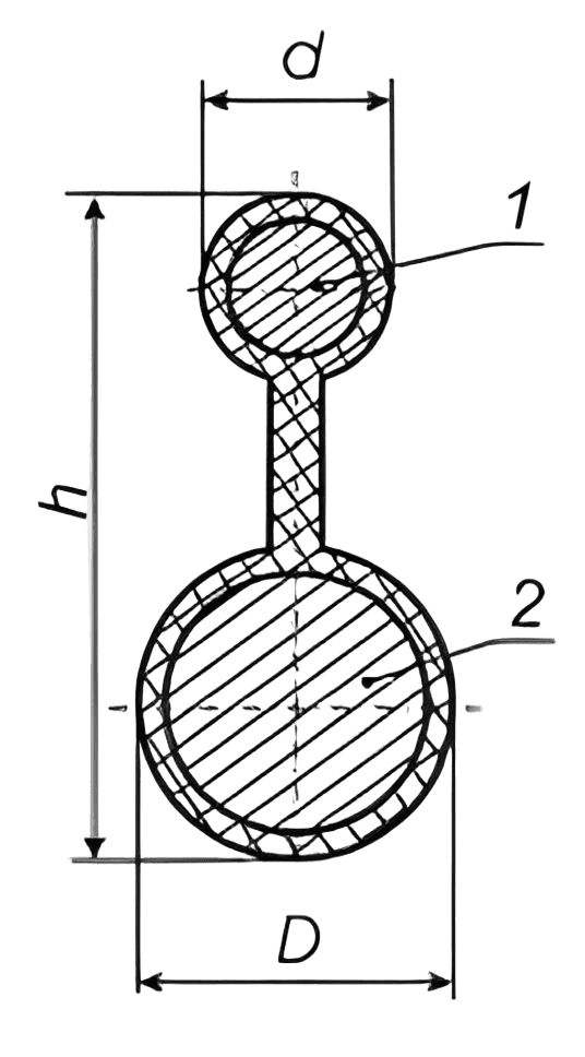
In cables of the U/UTP Cat 5e PE SC and F/UTP Cat 5e PE SC brands, the sheath is applied simultaneously over the cable core and a steel wire rope laid parallel through a separating web. By agreement with the customer, the cable may be manufactured with a rope made of galvanized steel wires.
The nominal diameter of the cable rope is 1.0 mm.
By agreement with the customer, cables may be manufactured with a different rope diameter.
Web dimensions: height from 1.5 mm to 2.0 mm inclusive, thickness from 0.9 mm to 1.2 mm.
The nominal sheath thickness of the rope is 0.8 mm, and the minimum thickness is 0.5 mm.
Manufacturing of cables by customer agreement:
– with a different class of conductive cores;
– with a different nominal core diameter;
– with a different number of twisted pairs or quads;
– with a colored outer sheath (red, white, blue, or another color).
If no specifications are provided in the order, the cables are manufactured with a black sheath.
| Parameter name | Standard |
| Electrical resistance of the conductive core to direct current, recalculated per 1000 m length at a temperature of 20 °C, Ohm, not more than: – for cables with a single-wire core – for cables with a multi-wire core | 95 145 |
| Ohmic imbalance of conductors in a working pair for cables of categories: – 3 and 5, %, not more than – 5e, 6, 6A, 7, 7A, %, not more than | 3 2 |
| Ohmic imbalance of conductors between pairs in cables of categories 5e, 6, 6A, 7, 7A, %, not more than | 4 |
| Electrical insulation resistance of conductive cores, recalculated per 1000 m length, MΩ, not less than: | 5000 |
| Test voltage between conductors and between all conductors and shields, kV: – direct current for 1 min – direct current for 2 s – alternating current at 50 Hz for 1 min – alternating current at 50 Hz for 2 s | 1 2.5 0.7 1.7 |
| Operating capacitance, recalculated per 1000 m length at a frequency of 0.8 kHz or 1.0 kHz, nF, not more than | 56 |
| Pair-to-ground capacitive imbalance for unshielded cables and pair-to-shield capacitive imbalance for shielded cables at a frequency of 0.8 or 1.0 kHz, recalculated per 1000 m length for cables of category: – 3 and 5, pF, not more than – 5e, 6, 6A, 7, 7A, pF, not more than | 3400 1600 |
| Name | Specifications |
| Ambient temperature, upper limit | + 60 °C |
| Ambient temperature, lower limit: | – 60 °C for cables with “PE” sheath – 40 °C for all other cables |
| Installation temperature, not below: – for cables with “PE” sheath; – for all others. | – 20 °C – 10 °C |
| Minimum permissible bending radius of cables | – 8 outer cable diameters |
| Service life of cables, not less than | 15 years |
| Warranty period of operation, not less than | 3 years |
0 шт.
цена за шт. - 0 ₽

Error: Contact form not found.
Error: Contact form not found.


