
To find out the cost of the cable, send the order code to our managers.
Delivery is carried out as soon as possible after the order is placed.
GERDA-KV, GERDA-KP, and GERDA-KPs cables are designed for data transmission at frequencies up to 4 MHz in measurement, control, and regulation technology, as well as for fixed inter-device installation of electrical instruments, apparatus, and devices operating at voltages up to 500V AC with a frequency of 50 or 60 Hz or up to 750V DC.
These cables can be used for forming digital information buses, connecting sensors with digital frequency-modulated signals, 4-20 mA signals, and interfacing via RS-485, RS-482, RS-422, as well as in Foundation Fieldbus, PROFIBUS, HART, and other systems requiring “twisted pair” for data transmission and reception.
The cables can be installed in explosive zones of all classes (in accordance with GOST IEC 60079-14-2013) and in open air (in compliance with GOST R 50571.5.52-2011). They can also be used in metro infrastructure facilities.
GERDA-KV, GERDA-KP, and GERDA-KPs cables are manufactured with tinned copper (by default) or untinned “m” multi-wire conductors of at least class 3, and for a cross-section of 0.35 mm², at least class 4.
The nominal conductor cross-sections and the number of pairs are specified in Table 2. It is allowed to manufacture cables with a different number of pairs and nominal conductor cross-sections, as well as with a combined conductor cross-section.
For fire-resistant “FR” cables, a wrapping of two mica-containing tapes is applied over the current-carrying conductors, preventing short circuits in the event of a fire.
The conductor insulation can be made of:
Conductor marking can be color-coded or numerical.
The conductors are twisted into pairs with a twist pitch of no more than 60 mm. In fire-resistant cables with a conductor cross-section of 1.5 mm² and 2.5 mm², the twist pitch is slightly larger to make the cable more circular and reduce its diameter.
Each conductor pair can have an individual shield:
An insulating polymer film is applied over the individual shield of each pair, preventing electrical contact between adjacent shields. Instead of a polymer film, an extruded polymer layer “v” can be applied, ensuring reliable insulation between pair shields.
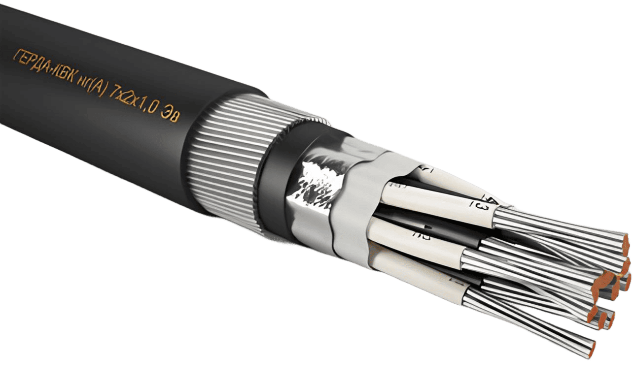
The conductor pairs are twisted into a core, over which a water-blocking tape is applied to prevent longitudinal moisture penetration in case of outer sheath damage. A common shield can be applied over the water-blocking tape.
Types of common shields:
An extruded separation layer is applied over the common shield, filling the free spaces between conductors (in accordance with GOST IEC 60079-14-2013). As a result, the cable cross-section becomes circular (allowing it to be used with any type of cable entry) and, in case of cable damage, an explosive gas mixture cannot penetrate under the sheath from the hazardous area into the safe area. By agreement with the customer, cables of non-circular shape (without extruded filling) can be manufactured.
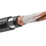
The cables can have armor made of galvanized steel wires “K” (GERDA-KVK, GERDA-KPK, GERDA-KPsK) or galvanized steel tapes “B” (GERDA-KVB, GERDA-KPB, GERDA-KPsB).
The cable sheath is made of PVC compounds or halogen-free polymer composition (see Table 3). The sheath color is determined in the order code. If not specified, the cables are manufactured in black.
| Conductor insulation material | |
| V | PVC plastic |
| P | Polymeric compositions |
| Ps | Cross-linked polyolefin |
| Armor under the outer sheath | |
| Without armor | |
| K | Wire armor |
| B | Tape armor |
| Number of twisted pairs |
| 1; 2; 3; 4; 5; 6; 7; 8; 9; 10; 12; 14; 15; 16; 19; 20; 21; 24; 27; 30; 37; 40; 44 |
| Conductor cross-section, mm² |
| 0.35; 0.5; 0.75; 1.0; 1.2; 1.5; 2.5 |
| Overall shield over the core of all twisted pairs. | |
| No overall shield | |
| Overall shield in the form of a copper wire braid | |
| Em | Copper wire braid |
| L | Tinned copper wire braid |
| Ea | Aluminum foil film |
| Emf | Copper foil film |
| EaL | Combined shield |
| Special characteristics | |
| No special characteristic | |
| HL | Increased cold resistance of cables |
| EHL | Resistance to extremely cold conditions |
| UV | UV-resistant throughout the cable’s service life |
| M | Oil and petrol-resistant design |
| H | Resistance to chemically aggressive environments |
| T | Increased heat resistance (up to +120°C) |
| ZG | Sheath resistant to damage from rodents, ants, termites |
| s | Cable with a blue sheath |
x
2 x
| Fire hazard rating |
| No index |
| ng(A) |
| ng(A)-LS |
| ng(A)-LSLTx |
| ng(A)-HF |
| ng(A)-HFLTx |
| ng(A)-FRLS |
| ng(A)-FRLSLTx |
| ng(A)-FRHF |
| ng(A)-FRHFLTx |
| Conductor tinning | |
| Tinned conductor | |
| m | Untinned conductor |
| Individual shielding of each pair | |
| Pairs do not have individual shielding | |
| e | Braid of tinned copper wires |
| em | Braid of copper wires |
| ea | Aluminum foil tape |
| emf | Copper foil tape |
| Insulation of individual pair shields (only for cables with individual pair shields) | |
| Individual pair shields are insulated from each other with polymer film | |
| v | Individual pair shields are insulated from each other with an extruded polymer layer |
* – Brackets are placed before the designation of pair “2” and after the cross-section and conductor type only when specifying an individual shield for each pair: “e”, “em”, “ea”, “emf”.
| Example of cable designation when ordering | Description |
| GERDA-KVK ng(A) 7x(2×0.5)e HL TU 3581-019-76960731-2010 | Installation cable with twisted pairs, featuring seven shielded pairs with tinned copper wire conductors of nominal cross-section 0.5 mm², no overall shield, conductor insulation made of PVC plastic compound, flame-retardant PVC sheath, steel galvanized wire armor under the outer sheath, frost-resistant version, operating temperature from –60º to +70ºC, installation down to –30ºC. |
| GERDA-KPsK ng(A)-FRLS 10x2x1.0m TU 3581-019-76960731-2010 | Installation cable with twisted pairs, fire-resistant, with cross-linked polyolefin insulation, ten pairs of copper conductors with a nominal cross-section of 1.0 mm², overall shield made of copper wires, wire armor, sheath made of low fire hazard PVC plastic compound, operating temperature from –50º to +70ºC, installation down to –15ºC. |
| GERDA-KP ng(A)-HF 19x(2×1.5)em Em EHL TU 3581-019-76960731-2010 | Installation cable with twisted pairs, featuring nineteen shielded pairs with a copper braid screen, tinned copper wire conductors with a nominal cross-section of 1.5 mm², insulation and sheath made of halogen-free polymer compounds, overall shield in the form of a copper wire braid, resistant to extreme cold conditions, operating temperature from –70º to +70ºC, installation down to –40ºC. |
| Operating Voltage |
– Up to 500 V AC with a frequency up to 4 MHz – Up to 750 V DC |
| Electrical Insulation Resistance at +20°C, not less than |
– 500 MΩ·km for cables with cross-linked polyolefin insulation – 50 MΩ·km for cables with halogen-free polymer insulation – 10 MΩ·km for cables with PVC insulation |
| Electrical Resistance of Conductors |
Complies with GOST 22483-2012. Electrical resistance of conductors with a nominal cross-section of 1.2 mm² should not exceed: – 17.6 Ω/km for tinned conductors – 17.3 Ω/km for non-tinned conductors (at +20°C) |
| Cable Testing with AC Voltage | 2000 V at 50 Hz for 1 min. |
| Maximum Capacitance at (1.0±0.1) kHz, recalculated for 1 km length at +20°C, not more than |
Between adjacent conductors: – 70 nF (cross-section 0.35-0.75 mm²) and 100 nF (cross-section 1.0-2.5 mm²) for cables with cross-linked polyolefin insulation – 140 nF (cross-section 0.35-0.75 mm²) and 180 nF (cross-section 1.0-2.5 mm²) for cables with PVC and halogen-free polymer insulation Between one conductor connected to the shield and another random conductor: – 180 nF for cables with cross-linked polyolefin insulation – 300 nF for cables with PVC and halogen-free polymer insulation |
| Maximum Cable Inductance at (1.0±0.1) kHz, recalculated for 1 km length at +20°C, not more than | 0.9 mH |
| Ohmic Imbalance of Conductors in a Pair | Not more than 3% |
| Operating Temperature |
– From –60°C to +70°C for cables with “HL” index – From –70°C to +70°C for cables with “EHL” index – From –50°C to +120°C for cables with “T” index – From –50°C to +70°C for other cable types |
| Minimum Installation Temperature, not lower than |
– Minus 40°C for cables with “EHL” index – Minus 30°C for cables with “HL” index – Minus 15°C for other cable types |
| Climatic Designation per GOST 15150-69 | Designation “B”, placement category 1-5, suitable for all macroclimatic regions, including tropical conditions. |
| Fire Resistance (for “FR” cables) |
Not less than 180 minutes under exposure to open flame and temperatures of at least +750°C (PO1 per GOST 31565-2012) |
| Resistance to Longitudinal Water Spread Under the Sheath | Fully blocked (all cables use a special water-blocking tape) |
| Resistance to Mold | Cables are resistant to mold growth, Mold growth rating: up to 2 points |
| Permissible Bending Radii During Installation and Operation, in D (outer cable diameter), not less than |
– 3D for non-armored cables – 4D for cables with wire armor – 5D for cables with tape armor – 7.5D for cables with “ZG” designation |
| Service Life, not less than | At least 25 years (not limited by the specified service life, determined by the technical condition of the cable) |
| Warranty Period | 2 years |
| Nominal Conductor Cross-Section, mm² | Number of Twisted Pairs (x2) |
| 0.35; 0.5; 0.75; 1.0; 1.2; 1.5; 2.5 | 1×2; 2×2; 3×2; 4×2; 5×2; 6×2; 7×2; 8×2; 9×2; 10×2; 12×2; 14×2; 15×2; 16×2; 19×2; 20×2; 21×2; 24×2; 27×2; 30×2; 37×2; 40×2; 44×2 |
| Insulation and Sheath Material Designation | Fire Safety Indicator | Description of Insulation and Sheath Material, as well as Cable Type According to Fire Safety Indicator (as per GOST 31565-2012) |
| V | – (no index) | cables with PVC insulation and sheath, non-flammable during single installation |
| ng(A) | cables with PVC insulation and low-combustibility PVC sheath, non-flammable during group installation | |
| ng(A)-LS | cables with low-hazard PVC insulation and sheath, non-flammable during group installation, with reduced smoke and gas emission | |
| ng(A)-LSLTx | cables with low-hazard PVC insulation and sheath, non-flammable during group installation, with reduced smoke and gas emission, and low toxicity of combustion products | |
| ng(A)-FRLS | fire-resistant cables with low-hazard PVC insulation and sheath, non-flammable during group installation, with reduced smoke and gas emission | |
| ng(A)-FRLSLTx | fire-resistant cables with low-hazard PVC insulation and sheath, non-flammable during group installation, with reduced smoke and gas emission, and low toxicity of combustion products | |
| P | ng(A)-HF | cables with insulation and sheath made of halogen-free polymer compounds, non-flammable during group installation and not emitting corrosive gaseous products during combustion and smoldering |
| ng(A)-HFLTx | cables with insulation and sheath made of halogen-free polymer compounds, non-flammable during group installation and not emitting corrosive gaseous products during combustion and smoldering, with low toxicity of combustion products | |
| ng(A)-FRHF | fire-resistant cables with insulation and sheath made of halogen-free polymer compounds, non-flammable during group installation and not emitting corrosive gaseous products during combustion and smoldering | |
| ng(A)-FRHFLTx | fire-resistant cables with insulation and sheath made of halogen-free polymer compounds, non-flammable during group installation and not emitting corrosive gaseous products during combustion and smoldering, with low toxicity of combustion products | |
| Ps | ng(A)-LS | cables with cross-linked polyolefin insulation and low-hazard PVC sheath, non-flammable during group installation, with reduced smoke and gas emission |
| ng(A)-FRLS | fire-resistant cables with cross-linked polyolefin insulation and low-hazard PVC sheath, non-flammable during group installation, with reduced smoke and gas emission | |
| ng(A)-HF | cables with cross-linked polyolefin insulation and halogen-free polymer sheath, non-flammable during group installation and not emitting corrosive gaseous products during combustion and smoldering | |
| ng(A)-FRHF | fire-resistant cables with cross-linked polyolefin insulation and halogen-free polymer sheath, non-flammable during group installation and not emitting corrosive gaseous products during combustion and smoldering |
| Frequency, kHz | Attenuation Coefficient, dB/100m, max | Wave Impedance, Ohms | ||
| Cables with Cross-Linked Polyolefin Insulation | Other Cable Types | Cables with Cross-Linked Polyolefin Insulation | Other Cable Types | |
| 1 | 0,15 | 1,25 | – | – |
| 39 | 0,50 | 4,49 | 120±15 | 80±20 |
| 1 000 | 2,60 | 18,61 | 100±15 | |
| 4 000 | 3,50 | 28,23 | 70±20 | |
0 шт.
цена за шт. - 0 ₽

Error: Contact form not found.
Error: Contact form not found.


