

To find out the cost of the cable, send the order code to our managers.
Delivery is carried out as soon as possible after the order is placed.
Telephone cables with polyethylene insulation in a plastic sheath of the brands TPPep, TPPepZ, TPV, TPVng, TPPShv (non-armored), TPPepBbShp, TPPepZBbShp, TPVBG, TPPBbShv (tape-armored), and TPPKShv (wire-armored) are designed for use in local primary communication networks with a nominal remote power voltage of up to 225 and 145 V AC at 50 Hz or up to 315 and 200 V DC, respectively.
Low-pair distribution cables of the brands MKPPep, MKPPepZ, and MKPPepT, with a nominal remote power voltage of up to 145, 225, and 350 V AC at 50 Hz or up to 200, 315, and 500 V DC, respectively, operating under excess air pressure or without pressure, are intended for installation in telephone ducts, in soil, in collectors, shafts, along external and internal building walls, and for suspension on overhead communication lines.
Station telephone cables of the TSV brand are designed for mounting low-frequency station equipment for general industrial applications, including equipment for both domestic and export markets.
Cables of the TPPep brand can be used for installation in all categories of soil that do not exhibit increased corrosive activity towards steel armor and are not subject to permafrost deformations.
Cables of the TPV brand can be used for installation along the interior walls of buildings and inside premises.
Cables of the TSV brand can be used for connecting telecommunications equipment, both in single installations and in group installations in areas of constant personnel presence.
Cable Construction
Telephone communication cables are manufactured with conductive cores made of soft round copper wire with nominal diameters of 0.32 mm, 0.4 mm, 0.5 mm, 0.64 mm, and 0.7 mm.
*By agreement with the customer, cables with a different number of pairs may be manufactured.
**Number of pairs or triples.
| Cable brand | Nominal number of pairs depending on conductor nominal diameter, mm | ||||
| 0.32 | 0.40 | 0.50 | 0.64 | 0.7 | |
| TPPep | 5-2400 | 5-1200 | 5-1200 | 5-600 | 5-600 |
| TPPepZ | 5-1200 | 5-1200 | 5-900 | 5-500 | 5-500 |
| TPPepBbShp | 10-600 | 10-600 | 10-600 | 10-500 | 10-500 |
| TPPepZBbShp | 10-300 | 10-300 | 10-300 | – | – |
| TPPept | – | – | 10-100 | 10-100 | 10-100 |
| TPV, TPVng | – | 10-100 | 10-100 | 10-100 | – |
| TPVBG | – | 10-100 | 10-100 | 10-100 | – |
| TPPShv, TPPShvng | – | 5-100 | 5-100 | 5-100 | 5-100 |
| TPPKShv, TPPKShvng, TPPBbShv, TPPBbShvng | – | 20-100 | 20-100 | 20-100 | 20-100 |
| TSV**, TSVng**, TSVng-LS** | – | 5, 10, 16, 20, 30, 41, 50, 103 | – | – | |
| MKPPep, MKPPepZ, MKPPepT | – | 1-5 | |||
The insulation of conductive cores is made of solid polyethylene in the form of a concentric layer, hermetically sealed, and free of foreign inclusions.
In cables with hydrophobic filling, polyethylene compatible with the hydrophobic filler is used.
Core
Two insulated conductors (a and b), distinctly different in color, are twisted into a pair using either unidirectional or bidirectional twisting.
For unidirectional twisting, the twist pitch does not exceed 100 mm.
For bidirectional twisting, the average pitch within one twist period does not exceed 100 mm, and the transition straight sections do not exceed 500 mm.
Pairs are twisted into elementary bundles (five-pair or ten-pair) or a core (for five-pair or ten-pair cables) using either unidirectional or bidirectional twisting of pairs, which are themselves twisted unidirectionally or bidirectionally, or by the wave twist system method using unidirectionally twisted pairs.
For unidirectional twisting, the twist pitch does not exceed 600 mm.
For bidirectional twisting, the average pitch within one twist period does not exceed 600 mm, and the transition straight sections do not exceed 800 mm.
Pairs in an elementary ten-pair bundle and a ten-pair core are color-coded according to Table 2.
| Pair number in the elementary bundle or core | Designation and color coding of conductors in the pair | Designation and color coding of conductors in the triplet (for “TSV”) | |
| a | b | ||
| 1 | White | Blue | Turquoise |
| 2 | Orange (Yellow) | ||
| 3 | Green | ||
| 4 | Brown | ||
| 5 | Gray (Black) | ||
| 6 | Red | Blue | |
| 7 | Orange (Yellow) | ||
| 8 | Green | ||
| 9 | Brown | ||
| 10 | Gray | ||
A binding wrap made of synthetic or cotton threads or synthetic tapes is applied to the elementary bundle in an open spiral.
Elementary bundles are twisted into a core or main 50- or 100-pair bundles using unidirectional or multidirectional twisting, while cable cores with up to 50 pairs inclusive are twisted using unidirectional or multidirectional twisting or the wave twisting method.
With unidirectional twisting, the average pitch does not exceed 75 diameters of the twisted core or main bundle. With multidirectional twisting, the average pitch within one twisting period does not exceed 75 diameters of the twisted core or main bundle, while the transitional straight sections do not exceed 2000 mm.
Elementary bundles in a 100-pair main bundle or core have a color coding as specified in Table 3.
Marking is allowed using a counting and guiding elementary bundle in each layer of the core or main bundle, differing from the other bundles by the color of the binding thread or tape.
| Conditional number of the elementary bundle | Color of binding elements |
| 1 | Blue |
| 2 | Orange |
| 3 | Green |
| 4 | Brown |
| 5 | Gray |
| 6 | White |
| 7 | Red |
| 8 | Black |
| 9 | Yellow |
| 10 | Purple |
Marking is allowed using a counting and guiding main bundle in each layer of the core, differing from the other bundles by the color of the binding thread or tape.
The counting 50- or 100-pair bundle is wrapped with a binding synthetic or cotton thread or a synthetic tape of red color, while the guiding bundle is wrapped with a thread or tape of green color (wrapping with a blue thread or tape is also allowed).
| Conditional number of the 100-pair counting group | Color of binding elements |
| 1 | Blue |
| 2 | Orange |
| 3 | Green |
| 4 | Brown |
| 5 | Gray |
| 6 | White |
| 7 | Red |
| 8 | Black |
| 9 | Yellow |
| 10 | Purple |
| 11 | White, blue |
| 12 | White, orange |
| 13 | White, green |
| 14 | White, brown |
| 15 | White, gray |
| 16 | Red, blue |
| 17 | Red, orange |
| 18 | Red, green |
| 19 | Red, brown |
| 20 | Red, gray |
| 21 | Yellow, blue |
| 22 | Yellow, orange |
| 23 | Yellow, green |
| 24 | Yellow, brown |
In cables of the TPPepZ, TPPepZBbShp brands, the free space of the core along its entire length is filled with a hydrophobic filler. The core of the filled cable is moisture-resistant.
The hydrophobic filler must not obscure the insulation colors, have an unpleasant odor, or be toxic and harmful to the skin.
A longitudinally overlapping sheath insulation made of polyamide, polyethylene, or polyethylene terephthalate tapes is applied over the twisted and filled core (for cables with hydrophobic filling).
Over the sheath insulation of cables with a filled core, a layer of hydrophobic filler is applied, which, together with the filled core, ensures the cable’s moisture resistance.
Shield
In TPPep brand cables, a longitudinally applied shield made of aluminum-polymer tape is placed over the sheath insulation.
In TPV brand cables, a shield made of aluminum-polymer tape is applied longitudinally or spirally over the sheath insulation.
In TSV brand cables, a shield made of aluminum or aluminum-polymer tape is applied longitudinally or spirally over the sheath insulation.
Aluminum and aluminum-polymer tapes with an aluminum layer of a nominal thickness of at least 0.10 mm are applied with an overlap of at least 15% for cables with a diameter under the sheath up to 20 mm inclusive and at least 10 mm for cables with a diameter under the sheath over 20 mm.
When using a two-layer shielding tape “aluminum-polyethylene,” the aluminum-polymer tape is applied to the cable with the metal side inward.
A tinned copper contact wire with a nominal diameter of 0.4 – 0.5 mm is laid under the shield. The use of a wire with a nominal diameter of 0.32 mm is allowed (by agreement with the consumer) for cables with conductors of a nominal diameter of 0.32 mm.
Sheath
Over the shield of TPPep brand cables, a sheath made of polyethylene is applied; for TPV, TPVBG, and TSV cables – made of polyvinyl chloride plastic; for TPVng and TSVng cables – made of low-flammability polyvinyl chloride plastic; and for TSVng-LS cable – made of low-hazard polyvinyl chloride plastic with reduced smoke and gas emissions.
Armor
Cables may have armor made of two galvanized steel tapes. In the TPPKShv cable, the armor consists of galvanized steel wires.
Outer sheath
A protective outer sheath (protective hose) is applied over the armor:
— “Shv” – made of PVC plastic;
— “Shvng” – made of low-flammability PVC plastic;
— “Shp” – made of polyethylene.
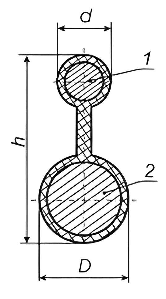
In TPPept brand cables, the sheath is applied simultaneously to the cable core and the steel wire rope (Figure 1). By agreement with the customer, the cable can be manufactured with a rope made of galvanized steel wires.
The nominal diameter of the rope for cables with a diameter under the sheath up to 20 mm inclusive is 3.1 mm, and for cables with a diameter over 20 mm, it is 3.7 mm.
The rope used in MKPPept brand cables has the following diameters:
— for single-pair cables – at least 1.0 mm;
— for 2 to 5-pair cables – at least 1.6 mm.
By agreement with the customer, cables can be manufactured with a rope of a different diameter.
If no specifications are provided in the order, cables are manufactured with a black sheath.
Cable manufacturing options by agreement with the customer:
— with length markings on the cable sheath;
— with a different number of twisted pairs;
— with a colored outer sheath (red, white, blue, or other colors).
The electrical parameters of the cables comply with the values specified in Table 5.
| Name | Characteristics |
| Electrical insulation resistance of conductive cores, recalculated per 1 km length at t=+20 °C, not less than (DC) | – 6500 MΩ for cables without hydrophobic core filling; – 5000 MΩ for cables with hydrophobic core filling. |
| Electrical insulation resistance of conductive cores, recalculated per 1 km length at t=+20 °C, not less than (DC) for TSV brand cables: | – 100 MΩ |
| Electrical resistance of conductive cores, recalculated per 1 km length at t=+20 °C, not more than (DC) | for a conductor diameter of 0.32 mm – 229 Ω; for a conductor diameter of 0.40 mm – 148 Ω; for a conductor diameter of 0.50 mm – 95 Ω; for a conductor diameter of 0.64 mm – 58 Ω; for a conductor diameter of 0.70 mm – 48 Ω. |
| Test voltage applied for 1 min (current frequency 0.05 kHz): – between conductors and shield for cables rated up to 500 V DC – between conductors and shield for cables rated up to 315 V DC – between conductors and shield for cables rated up to 200 V DC – between working pair conductors | 50 Hz DC: 2500 V / 4000 V 50 Hz DC: 2000 V / 3000 V 50 Hz DC: 500 V / 750 V 50 Hz DC: 1000 V / 1500 V |
| Test voltage applied between conductors and shield for 1 min, not less than for TSV brand cables: AC voltage at 50 Hz / DC voltage | 1000 V 1500 V |
| Operating capacitance, recalculated per 1 km length, not more than (current frequency 0.8 or 1.0 kHz, for cables rated up to 200 V): – for cables without hydrophobic filler – for cables with hydrophobic filler | 45±5 nF; 50±5 nF. |
| Note: Other electrical parameters not specified in the table comply with GOST 31943-2012, ST RK 2340-2013, ST RK 2204-2012, ST RK 2528-2014 | |
| Ambient temperature, upper limit | +60 °C (for TSV brand cables +50 °C) |
| Ambient temperature, lower limit | -50 °C (for TSV brand cables -20 °C) |
| Installation temperature, not below: – for cables with a polyethylene sheath without hydrophobic filler – for all others | -15 °C -10 °C |
| Minimum allowable bending radius: | – 12 calculated outer diameters of the cable – for armored cables; – 10 calculated outer diameters of the cable; – for non-armored cables with a shield. |
| Service life of cables, not less than: – for TPPep, MKPPep, and TPPShv brand cables – for TSV brand cables | 20-25 years depending on the cable brand 15 years |
| Warranty period of operation, not less than | 3 years |
0 шт.
цена за шт. - 0 ₽

Error: Contact form not found.
Error: Contact form not found.


