
To find out the cost of the cable, send the order code to our managers.
Delivery is carried out as soon as possible after the order is placed.
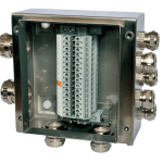
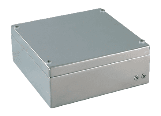
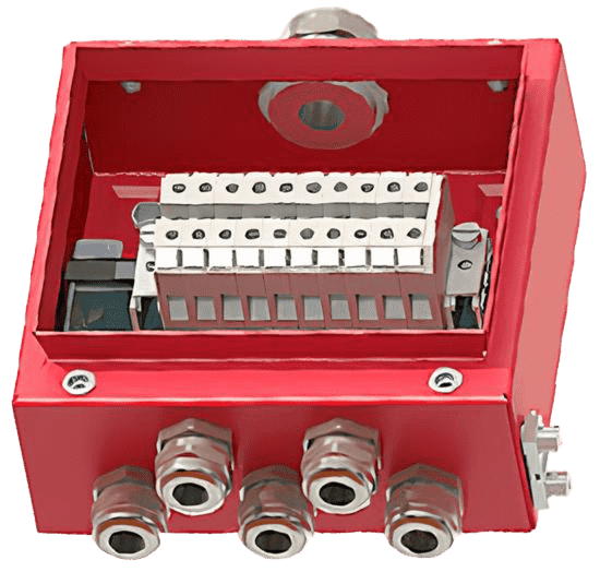
Explosion-proof junction boxes are designed for connecting and branching armored and non-armored cables with copper or aluminum conductors in AC or DC circuits.
Hazardous areas in indoor and outdoor installations in accordance with Ex-marking and GOST IEC 60079-14, which regulate the use of electrical equipment in explosive gas and dust environments. Climatic version B, placement category 1–5 according to GOST 15150.
The boxes comply with the requirements of the following standards: GOST 31610.0, GOST IEC 60079-1, GOST 31610.7, GOST 31610.11, GOST IEC 60079-31, GOST IEC 60079-14, as confirmed by the certificate of conformity with the technical regulations of the Eurasian Economic Union TR CU 012/2011 “On the safety of equipment for use in explosive environments.” Certificate registration number: EAEU RU С-RU.АА87.В.01227/23. By decisions of the EEC Board dated 22.11.2022 No. 182 and 01.12.2020 No. 158, amendments were made to the lists of standards required for application and compliance with TR CU 012/2011 “On the safety of equipment for use in explosive environments.” As a result, from 30.06.2023, a significant number of standards were excluded from TR CU 012/2011, and new standards were introduced. The new standards have revised requirements for Ex-marking. Aluminum GERDA-KSA and stainless steel GERDA-KSN junction boxes have successfully passed certification for compliance with TR CU 012/2011 under the new standard requirements and received updated Ex-marking.
The boxes are certified under the voluntary certification system INTERGAZSERT. Certificate registration number: OGN4.RU.1103.B02847.
Certification details are available in the Rosaccreditation register
| Ex-marking | 1Ex eb IIC T6…T4 Gb X 1Ex ia IIC T6…T4 Gb X 1Ex eb db IIC T6…T4 Gb X 1Ex eb [ia] IIC T6…T4 Gb X Ex tb IIIC T85°C…T135°C Db X | |||
| Degree of protection against external influences (IP code) according to GOST 14254 | IP66 | |||
Ambient temperature range, °C:
| Minimum temperature, °C | Maximum temperature, °C depending on the temperature class | ||
| T6 (T85°C) | T5 (T100°C) | T4 (T135°C) | ||
| -40 -60 | +40 | +55 | +95 | |
| Maximum voltage 1, V | 1500 | |||
| Maximum current 1, A | 500 | |||
| Maximum cable core cross-section 1, mm² | 240 | |||
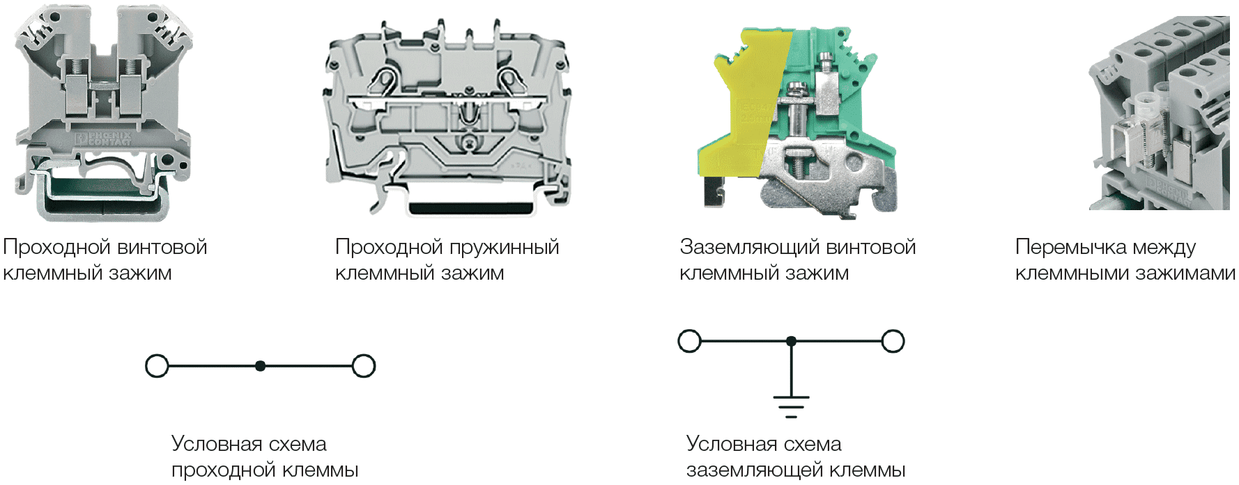
| Type of core fastening in terminal clamp 1 | screw (default) or spring (P) | |||
Box body coating:
|
| |||
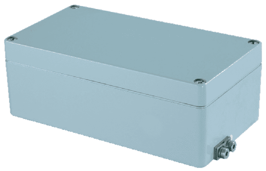
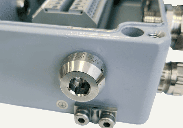
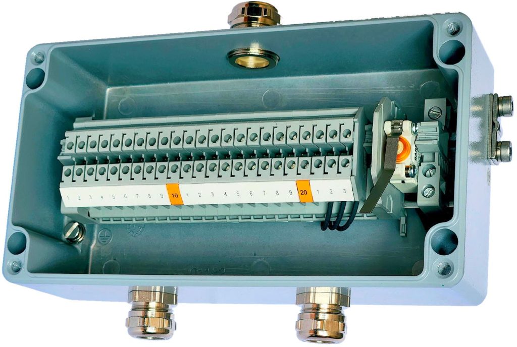
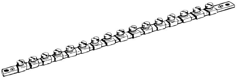
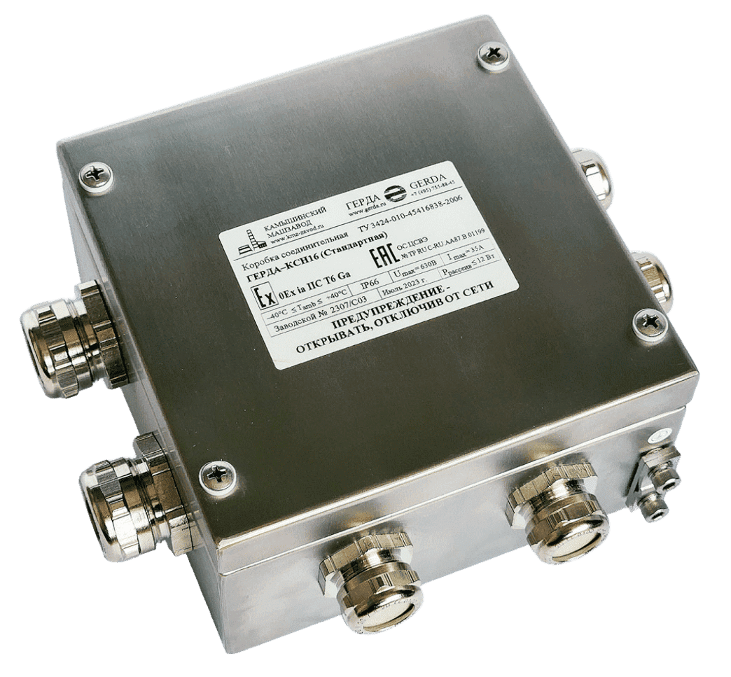
The body and cover of the GERDA-KSA box are made of aluminum, while the body and cover of the GERDA-KSN box are made of stainless steel. A silicone gasket between the body and the cover ensures the required degree of protection against external influences. The body and cover are secured with captive stainless steel screws. Ex cable glands are located on the end walls of the body. Inside the body, connection terminals (clamps, terminal blocks) are installed on a mounting rail, certified for compliance with the requirements of TR CU 012/2011 “On the safety of equipment for use in explosive environments.”
The boxes may also include Ex components certified for compliance with TR CU 012/2011 requirements: switches, selectors, push buttons, signal lamps, distribution buses, measuring instruments, and other electrical equipment in accordance with the manufacturer’s technical documentation.
The body size, type and number of terminal clamps, as well as the type and number of cable glands, are determined by the designation of the junction box. The designation scheme for ordering a junction box is provided below.
To simplify ordering, an abbreviated designation (“Standard Junction Box”) may be used. The composition of the “Standard Junction Box” is fully predefined and specified below.
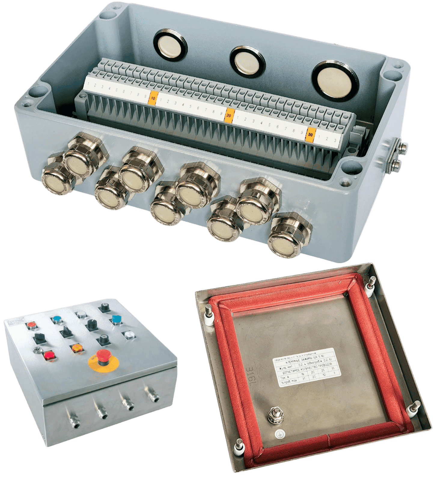
According to the new requirements of the standards included in the TR CU 012/2011 list, an additional label must be applied to the box cover, providing information on the permissible range of conductor cross-sections, the maximum current value for each conductor cross-section, and the maximum number of wires in the box.
| GERDA-KV | GERDA-KVM | GERDA-KVRV | GERDA-KVRN | GERDA-KVTr |
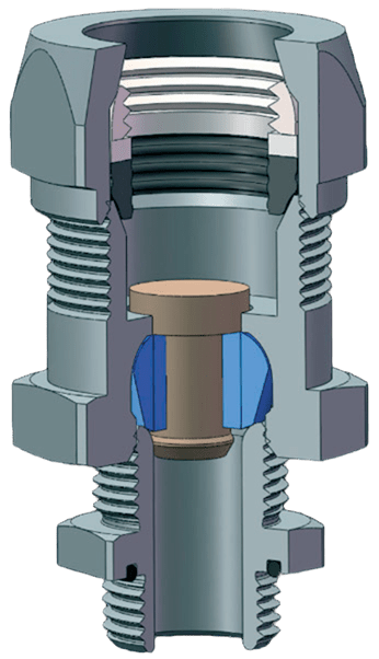
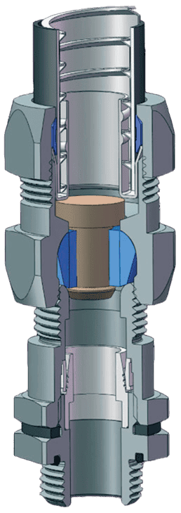
| For all types of non-armored cables | For round-section non-armored cables installed in a sealed metal conduit GERDA-MG. The conduit is directly connected to the gland | With an internal thread at the end, for all types of round-section non-armored cables installed in a pipe or metal conduit. The pipe requires threading, and the conduit needs a connector | With an external thread at the end, for all types of round-section non-armored cables installed in a pipe or metal conduit. The pipe requires threading, and the conduit needs a connector | With a collet clamping device for securing the pipe, for all types of round-section non-armored cables installed in a pipe. No threading is required on the pipe |
armor type: steel tape, single-layer steel wire, steel braided mesh
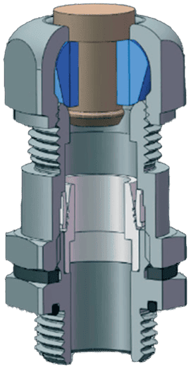
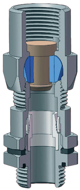
| GERDA-KVB | GERDA-KVBM | GERDA-KVBRV | GERDA-KVBRN | GERDA-KVBT |
| for all types of armored round-section cables | for all types of armored round-section cables laid in the GERDA-MG sealed metal conduit. The metal conduit is directly connected to the gland | with an internal thread at the end, for all types of armored round-section cables laid in a pipe or metal conduit. The pipe must be threaded, and a connector is required for the metal conduit | with an external thread at the end, for all types of armored round-section cables laid in a pipe or metal conduit. The pipe must be threaded, and a connector is required for the metal conduit | with a collet pipe fastening device, for all types of armored round-section cables laid in a pipe. No threading is required on the pipe |

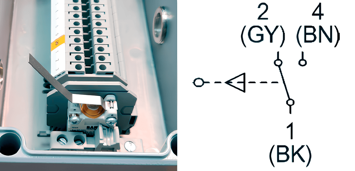
Junction box with a cover opening sensor
| ORDER DESIGNATION | THREAD | ALTERNATIVE DESIGNATION |
| C1 | M20 x 1.5 | RZ 20 |
| C2 | M25 x 1.5 | RZ 25 |
| C3 | M32 x 1.5 | RZ 32 |
| C4 | M40 x 1.5 | RZ 40 |
| C5 | M50 x 1.5 | RZ 50 |
| C6 | M63 x 1.5 | RZ 63 |
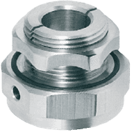
| ORDER DESIGNATION | THREAD |
| USC | M20 x 1.5 |
| ORDER DESIGNATION | DESCRIPTION |
| KNK | Set of 4 pcs. with screws and washers |
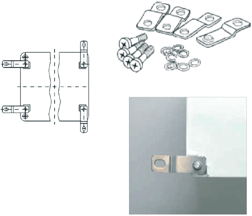
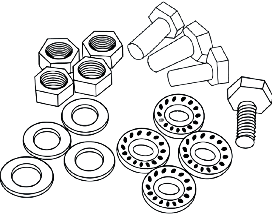
| ORDER DESIGNATION | DESCRIPTION |
| KNK | Set of 4 pcs. with screws, nuts, and washers |
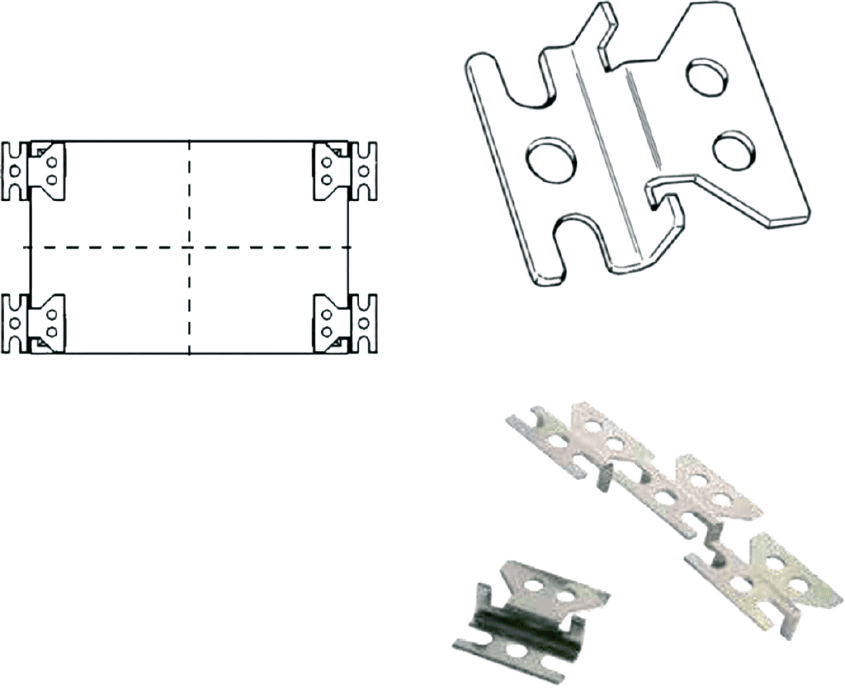
| ORDER DESIGNATION | DESCRIPTION |
| MK | Set of 4 pcs. with screws, nuts, and washers |
| ORDER DESIGNATION | DESCRIPTION |
| SZ | Grounding busbar with clamps, electrically connected to the housing |
| ISZ | Grounding busbar with clamps, electrically insulated from the housing |
| ORDER DESIGNATION | DESCRIPTION |
| NP | Box with installed lid hinges |
| ORDER DESIGNATION | DESCRIPTION |
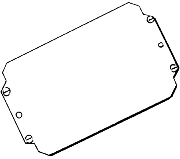
| MP | Plate installed inside the box housing |
| ORDER DESIGNATION | DESCRIPTION |
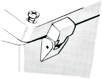
| BP | Bolt installed in the box cover |
| ORDER DESIGNATION | DESCRIPTION |
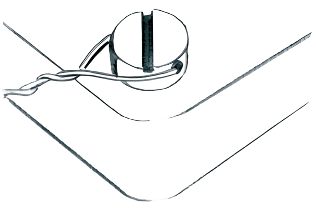
| DV | Sensor installed on a DIN rail, connected to three terminal clamps of the box |
| GERDA-KS | A | 12 | ( | 10 | , | 2 | ) | 2.5 | P | – | 2 | KV | 20 | ( | A | ) | … | – | 1 | KVM | 25 | ( | B | ) | – | HL | – | 1Ex eb IIC T6 Gb X |
| 1 | 2 | 3 | 4 | 5 | 6 | 7 | 8 | 9 | 10 | 7 | 8 | 9 | 10 | 11 | 12 |
| Parameter Name | Code in Designation2 | Explanation | |
| 1 | Enclosure Material | A | Aluminum |
| N | Stainless Steel | ||
| 2 | Box Size1 | 5 … 348 | Size corresponds to the maximum number of terminals for wires up to 4 mm² that can be installed in the box — see pages 21, 23–24 (GERDA-KSA), page 27 (GERDA-KSN) |
| 3 | Number of Through Terminals | 0 … 412 | The total number of terminals (through + grounding) must not exceed the value specified in the table for GERDA-KSA and GERDA-KSN |
| 4 | Number of Grounding Terminals | ||
| 5 | Terminal Size – Defined by Maximum Conductor Cross-section | 1.5; 2.5; 4; 6; 10; 16; 25; 35; 50; 70; 95; 150; 240 | If left blank, terminals of size “4” will be installed – for multi-stranded wires up to 4 mm² |
| 6 | Special Terminal Design | – | Leave blank for screw terminals |
| P | Spring-loaded terminal clamps | ||
| K | Ceramic terminal clamps (used in fire-resistant boxes “FR”) | ||
| 7 | Number of Cable Glands or Threaded Plugs on the Specified Side | 1 … 270 | The total number of cable glands and threaded plugs must not exceed the maximum value specified in the table for GERDA-KSAand GERDA-KSN |
| 8 | Cable Gland or Threaded Plug Designation | KV, KVM, KVRV, KVRN, KVTp, KVB, KVBM, KVBRV, KVBRN, KVBTr, L, KM, B, BD, S, RZ | See the “Cable Glands” section for designation details |
| 9 | Thread Size of Cable Gland or Threaded Plug | 1, 2, 3, 4, 5, 6 or 20, 25, 32, 40, 50, 63 | Thread size is determined when selecting a cable gland |
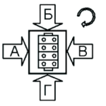
| 10 | Side Location of Cable Gland or Threaded Plug | A, B, C, D | The external grounding clamp is located on side “D” |
| 11 | Special Versions and Accessories (Multiple Indexes are Listed with a Dash or Comma) | HL, FR, SZ, ISZ, KNK, USC, MP, NP, BP, DV | HL – Resistance to low temperatures down to -60°C, FR – Fire-resistant GERDA-KSN box with ceramic terminals for fire-resistant wiring according to GOST R 53316 and PAZ (ESD), SZ – Grounding bus, ISZ – Electrically insulated grounding bus, KNK – Wall mounting bracket, USC – Condensate drainage device, MP – Mounting plate, NP – External lid hinges, BP – Sealed lid bolts, DV – Ex-opening detection sensor. See “Accessory Selection” for details. |
| 12 | Ex Marking | 1Ex eb IIC T6…T4 Gb X, 1Ex ia IIC T6…T4 Gb X, 1Ex eb db IIC T6…T4 Gb X, 1Ex eb [ia] IIC T6…T4 Gb X, Ex tb IIIC T85…135°C Db X | The temperature class T must be determined in the Ex marking, for example: 1Ex eb IIC T6 Gb X |
NOTE:
1 — It is recommended to choose the GERDA-KSA size from the stock program of junction boxes, the list of which is specified in the table GERDA-KSA.
2 — For standard junction boxes, the composition is fully predefined and specified. A simplified designation is used for these boxes: positions 3…10 are left blank, and after position 12, “(Standard)” is indicated. For example: GERDA–KSA9–1Ex ia IIC T6 Gb X (Standard).
Examples of junction box designation when ordering:
GERDA–KSA26(20.0)P–1KV32(A)–2KVM25(B)–ISHZ–1Ex ia IIC T4 Gb X TU 3424-010-45416838-2006 GERDA–KSA12–HL–1Ex eb IIC T6 Gb X (Standard) TU 3424-010-45416838-2006
| GERDA Junction Box Type | Enclosure Size, W×L×H, mm | Maximum Number of Terminals for Conductors with Cross-Section, mm² | DIN Rail | Max. Number of Cable Glands Type “KV” or “L” on One Side (A, B, C, D). For All Other Types of Glands — Max. Quantity is Half of the Indicated Value. If Different Sizes Are Used on One Side, Consider the Percentage Ratio. | Max. Dissipated Power, W | Weight, g | ||||||||||||||||||
| Size | Max. Quantity | M20 | M25 | M32 | M40 | M50 | M63 | |||||||||||||||||
| 2.5 | 4 | 6 | 10 | 16 | 35 | 50 | A/V | B/G | A/V | B/G | A/V | B/G | A/V | B/G | A/V | B/G | A/V | B/G | ||||||
| KSA 5 | 80x75x57 | 8 | 7 | · | · | · | · | · | TS 15 | 1 | 2 | 1 | 1 | 1 | · | · | · | · | · | · | · | · | 10 | 300 |
| KSA 13 | 80x125x57 | 16 | 13 | · | · | · | · | · | TS 15 | 1 | 3 | 2 | 2 | 1 | · | · | · | · | · | · | · | · | 15 | 375 |
| KSA 21 | 80x175x57 | 26 | 21 | · | · | · | · | · | TS 15 | 1 | 5 | 2 | 3 | 1 | · | · | · | · | · | · | · | · | 20 | 550 |
| KSA 32 | 80x250x52 | 40 | 33 | · | · | · | · | · | TS 15 | 1 | 8 | 2 | 5 | 1 | · | · | · | · | · | · | · | · | 25 | 730 |
| KSA 9 | 100x100x81 | 11 | 9 | 7 | · | · | · | · | TS 35 | 1 | 5 | 3 | 2 | 1 | 1 | 1 | · | · | · | · | · | · | 19 | 620 |
| KSA 19 | 100x160x81 | 23 | 19 | 14 | · | · | · | · | TS 35 | 1 | 10 | 3 | 4 | 1 | 3 | 1 | · | · | · | · | · | · | 26 | 820 |
| KSA 24 | 100x200x81 | 30 | 25 | 19 | · | · | · | · | TS 35 | 1 | 12 | 3 | 5 | 1 | 3 | 1 | · | · | · | · | · | · | 31 | 970 |
| KSA 10 | 120x122x81 | 12 | 10 | 7 | 6 | 5 | · | · | TS 35 | 1 | 4 | 4 | 2 | 2 | 1 | 1 | · | · | · | · | · | · | 24 | 940 |
| KSA 11 | 120x122x91 | 12 | 10 | 7 | 6 | 5 | · | · | TS 35 | 1 | 4 | 4 | 2 | 2 | 1 | 1 | · | · | · | · | · | · | 26 | 960 |
| KSA 25 | 120x220x81 | 31 | 26 | 20 | 16 | 13 | · | · | TS 35 | 1 | 12 | 4 | 5 | 2 | 3 | 1 | · | · | · | · | · | · | 38 | 1410 |
| KSA 26 | 120x220x91 | 31 | 26 | 20 | 16 | 13 | · | · | TS 35 | 1 | 14 | 4 | 6 | 2 | 4 | 1 | · | · | · | · | · | · | 40 | 1430 |
| KSA 47 | 120x360x81 | 58 | 49 | 37 | 29 | 25 | · | · | TS 35 | 1 | 24 | 4 | 10 | 2 | 7 | 1 | · | · | · | · | · | · | 57 | 1970 |
| KSA 12 | 140x140x91 | 16 | 13 | 10 | 8 | 7 | · | · | TS 35 | 1 | 8 | 4 | 3 | 2 | 2 | 1 | · | · | · | · | · | · | 32 | 1520 |
| KSA 22 | 140x200x91 | 26 | 22 | 17 | 13 | 11 | · | · | TS 35 | 1 | 12 | 4 | 5 | 2 | 3 | 1 | · | · | · | · | · | · | 42 | 2270 |
| KSA 16 | 160x160x91 | 20 | 16 | 12 | 10 | 8 | 6 | · | TS 35 | 1 | 9 | 6 | 5 | 3 | 3 | 2 | 2 | 1 | 2 | · | · | · | 39 | 1500 |
| KSA 33 | 160x260x91 | 39 | 33 | 25 | 20 | 16 | 12 | · | TS 35 | 1 | 17 | 6 | 10 | 3 | 5 | 2 | 3 | 1 | 3 | · | · | · | 56 | 2030 |
| KSA 48 | 160x360x91 | 58 | 49 | 37 | 29 | 25 | 18 | · | TS 35 | 1 | 24 | 6 | 15 | 3 | 7 | 2 | 5 | 1 | 4 | · | · | · | 73 | 2540 |
| KSA 81 | 160x560x91 | 97 | 81 | 61 | 49 | 41 | 31 | · | TS 35 | 1 | 40 | 6 | 24 | 3 | 12 | 2 | 8 | 1 | 6 | · | · | · | 107 | 3760 |
| KSA 20 | 180x180x101 | 24 | 20 | 15 | 12 | 10 | 8 | · | TS 35 | 1 | 11 | 8 | 6 | 3 | 3 | 2 | 2 | 2 | 2 | · | · | · | 49 | 2270 |
| KSA 35 | 180x280x101 | 42 | 35 | 27 | 21 | 18 | 13 | · | TS 35 | 1 | 18 | 8 | 11 | 4 | 5 | 2 | 4 | 2 | 3 | · | · | · | 68 | 2920 |
| KSA 28 | 230x100x111 | 33 | 28 | 17 | 21 | 18 | 13 | · | TS 35 | 1 | 6 | 17 | 3 | 8 | 2 | 5 | 1 | 3 | 1 | 2 | · | 2 | 45 | 1800 |
| KSA 44 | 232x202x111 | 54 | 46 | 34 | 14 | 10 | 9 | · | TS 35 | 2 | 18 | 17 | 8 | 8 | 6 | 5 | 3 | 3 | 2 | 2 | 2 | 2 | 68 | 2440 |
| KSA 46 | 232x202x181 | 54 | 46 | 34 | 14 | 11 | 9 | 8 | TS 35 | 2 | 33 | 33 | 18 | 16 | 10 | 9 | 6 | 6 | 5 | 5 | 4 | 4 | 92 | 3980 |
| KSA 72 | 230x280x111 | 86 | 72 | 54 | 44 | 18 | 13 | · | TS 35 | 2 | 24 | 17 | 12 | 8 | 9 | 5 | 4 | 3 | 3 | 2 | 3 | 2 | 86 | 2990 |
| KSA 86 | 230x330x111 | 104 | 88 | 66 | 52 | 22 | 16 | · | TS 35 | 2 | 30 | 17 | 15 | 8 | 11 | 5 | 5 | 3 | 4 | 2 | 4 | 2 | 97 | 3390 |
| KSA 88 | 230x330x181 | 104 | 88 | 66 | 52 | 22 | 16 | 14 | TS 35 | 2 | 60 | 33 | 30 | 16 | 18 | 9 | 11 | 6 | 8 | 5 | 8 | 4 | 127 | 5260 |
| KSA 109 | 230x400x111 | 130 | 110 | 82 | 66 | 28 | 21 | · | TS 35 | 2 | 39 | 17 | 20 | 8 | 14 | 5 | 6 | 3 | 5 | 2 | 5 | 2 | 113 | 3840 |
| KSA 110 | 230x400x225 | 130 | 110 | 82 | 66 | 28 | 21 | 18 | TS 35 | 2 | 100 | 44 | 54 | 21 | 30 | 13 | 18 | 9 | 15 | 6 | 12 | 5 | 167 | 6840 |
| KSA 174 | 230x600x111 | 206 | 174 | 132 | 53 | 44 | 33 | · | TS 35 | 2 | 54 | 17 | 28 | 8 | 20 | 4 | 10 | 3 | 8 | 2 | 6 | 2 | 159 | 6950 |
| KSA 162 | 313x404x111 | 195 | 165 | 123 | 66 | 28 | 21 | · | TS 35 | 3 | 39 | 26 | 20 | 12 | 14 | 7 | 6 | 4 | 5 | 3 | 5 | 3 | 145 | 5300 |
| KSA 163 | 312x403x141 | 195 | 165 | 123 | 66 | 28 | 21 | 18 | TS 35 | 3 | 55 | 32 | 28 | 18 | 17 | 10 | 12 | 7 | 7 | 4 | 6 | 3 | 160 | 6720 |
| KSA 164 | 313x404x181 | 195 | 165 | 123 | 66 | 28 | 21 | 18 | TS 35 | 3 | 78 | 51 | 40 | 24 | 22 | 15 | 15 | 9 | 11 | 6 | 8 | 6 | 183 | 8480 |
| KSA 165 | 313x404x227 | 195 | 165 | 123 | 66 | 28 | 21 | 18 | TS 35 | 3 | 100 | 68 | 54 | 33 | 30 | 20 | 18 | 12 | 15 | 9 | 12 | 8 | 208 | 8680 |
| KSA 260 | 310x600x111 | 309 | 261 | 132 | 106 | 88 | 33 | · | TS 35 | 3 | 60 | 24 | 30 | 12 | 20 | 7 | 10 | 4 | 8 | 3 | 6 | 3 | 199 | 8660 |
| KSA 261 | 310x600x181 | 309 | 261 | 132 | 106 | 88 | 33 | 28 | TS 35 | 3 | 108 | 48 | 56 | 24 | 32 | 15 | 22 | 9 | 16 | 6 | 12 | 6 | 246 | 11100 |
| KSA 348 | 600x600x202 | 412 | 348 | 198 | 159 | 132 | 66 | 56 | TS 35 | 4 | 108 | 108 | 56 | 56 | 32 | 32 | 22 | 22 | 16 | 16 | 12 | 12 | 428 | 25960 |
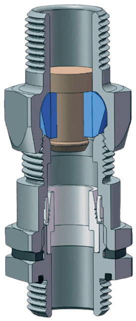
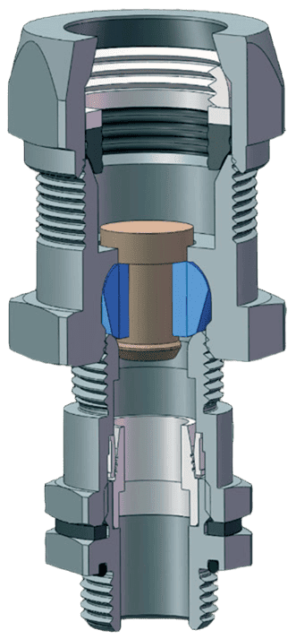
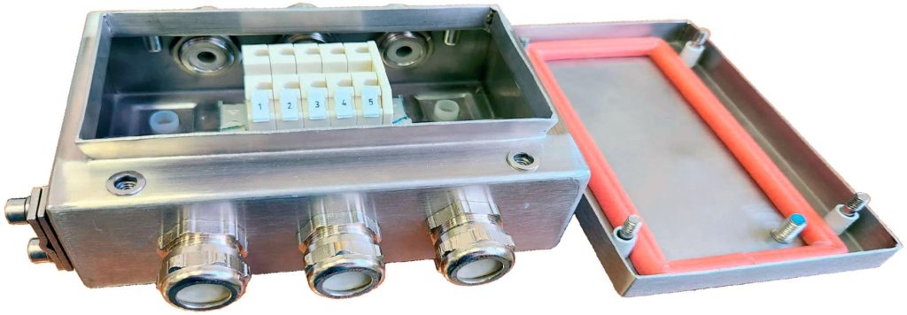
Standard junction boxes are designed as a rectangular housing with a cover, connected by captive stainless steel screws. Inside the housing, terminal clamps for conductors with a cross-section of 0.2 – 4 mm² are mounted on a DIN rail. The terminals are numbered sequentially, starting from “1.” Nickel-plated brass cable glands are located on the side surfaces of the housing.
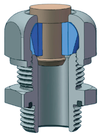
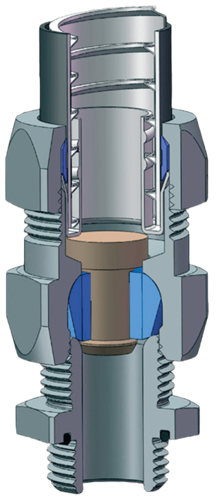
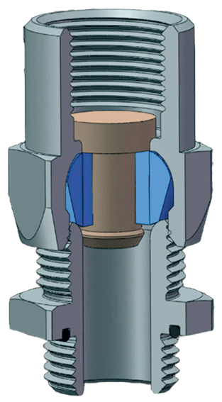
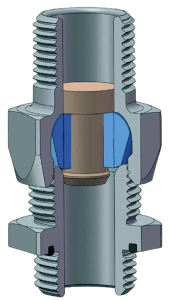
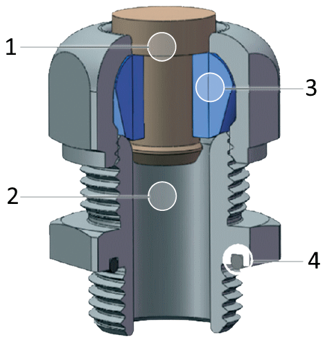
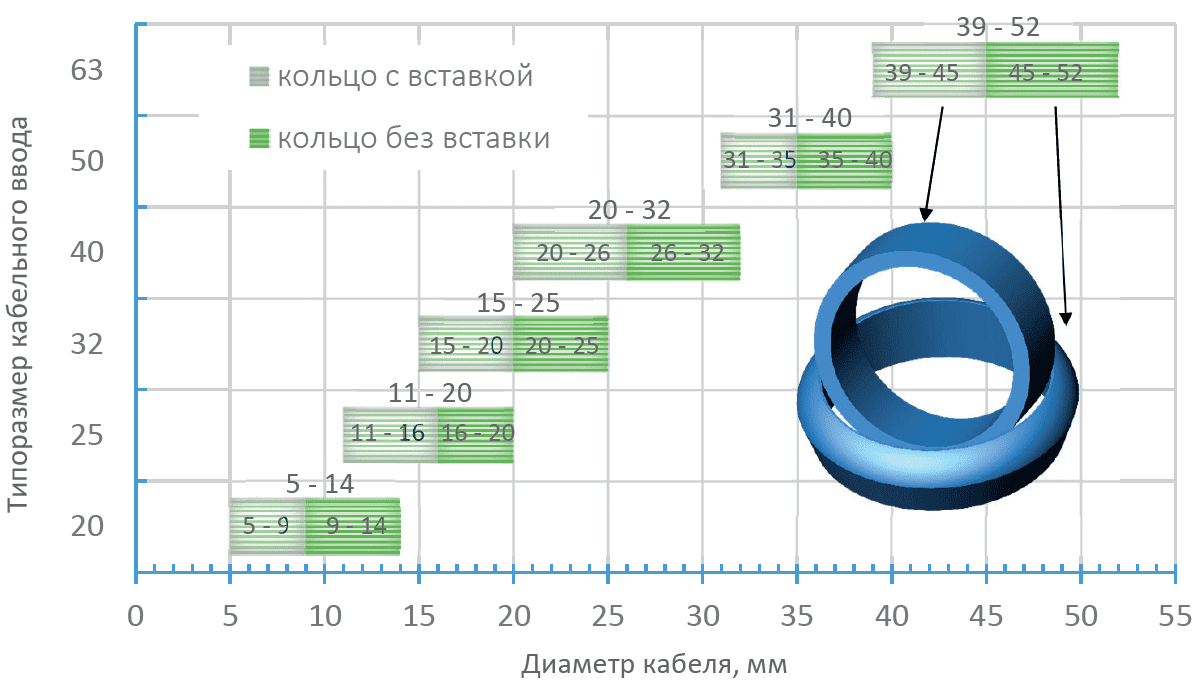
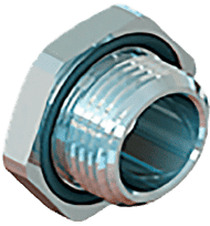
Explosion-proof plugs are installed in the cable glands, allowing the box to be used with empty entries (without cables) while maintaining the specified level of explosion protection and the degree of protection against external influences (IP). When inserting a cable, the plug is removed and replaced with a sealing ring of the required diameter — all rings are included in the supply package. The box has both an external and an internal grounding clamp.
The junction box is easy to choose from among 8 standard sizes of GERDA-KSA aluminum housings and 4 GERDA-KSN stainless steel housings. The boxes are supplied with terminal clamps and cable glands — the quantity and size are specified in the table “Standard Junction Box Specifications”.
| GERDA Box Type | KSA5 | KSA9 | KSA12 | KSA16 | KSA26 | KSA33 | KSA48 | KSA86 | |
| Number of Installed | Terminals for conductors up to 4 mm² | 5 | 9 | 12 | 16 | 26 | 33 | 48 | 86 |
| Cable Glands | 3 | 4 | 7 | 10 | 11 | 12 | 17 | 37 | |
| Box Dimensions L×W×H, mm | With Cable Glands | 95x120x57 | 140x140x80 | 165x180x90 | 185x200x90 | 220x165x90 | 260x210x90 | 360x210x90 | 385x280x111 |
| Housing (without glands) | 75x80x57 | 100x100x80 | 140x140x90 | 160x160x90 | 220x120x90 | 260x160x90 | 360x160x90 | 330x230x111 | |
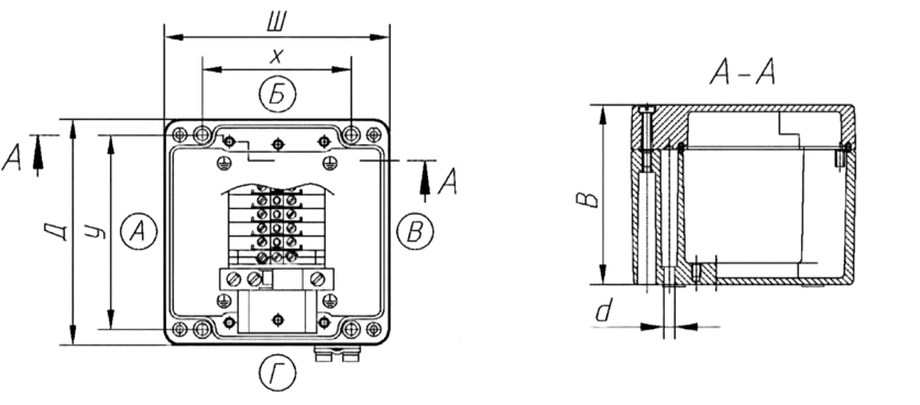
| Mounting Dimensions, mm | x×y | 52×63 | 66×86 | 93×120 | 110×140 | 82×204 | 110×240 | 110×340 | 180×310 |
| d | 4.8 | 4.8 | 7 | 7 | 7 | 7 | 7 | 7 | |
| Box Weight, g | 430 | 750 | 1650 | 2000 | 2100 | 2900 | 3950 | 6000 | |
| Side of the box → Gland thread size (cable diameter) ↓ | A | B | V | G | A | B | V | G | A | B | V | G | A | B | V | G | A | B | V | G | A | B | V | G | A | B | V | G | A | B | V | G | |
 | М20×1,5 (Ø5-13) | 1 | 1 | 1 | 9 | 15 | 15 | ||||||||||||||||||||||||||
| М25×1,5 (Ø7-15,5) | 1 | 1 | 1 | 1 | 3 | 3 | 4 | 4 | 9 | 13 | |||||||||||||||||||||||
| М32×1,5 (Ø11,5-20,5) | 1 | 2 | 2 | 2 | 2 | 2 | 2 | ||||||||||||||||||||||||||
| М40×1,5 (Ø20,0-28,0) | 1 | 1 | 2 | ||||||||||||||||||||||||||||||
| М50×1,5 (Ø27,0-36,0) | 1 | 1 | |||||||||||||||||||||||||||||||
| GERDA Box Type | KSN7 | KSN15 | KSN16 | KSN40 | |
| Number of Installed | Terminals for conductors up to 4 mm² | 7 | 15 | 16 | 40 |
| Cable glands | 3 | 6 | 9 | 12 | |
| Box Dimensions L×W×H, mm | With cable glands | 121x142x61 | 150x142x61 | 171x196x81 | 300x196x81 |
| Housing (without glands) | 100x100x61 | 150x100x61 | 150x150x81 | 300x150x81 | |
| Mounting Dimensions, mm | x×y | 60×60 | 60×110 | 110×110 | 110×260 |
| d | 10 | 10 | 10 | 10 | |
| Box Weight, g | 665 | 991 | 1695 | 2815 | |
| Side of the box → Gland thread size (cable diameter) ↓ | A | B | V | G | A | B | V | G | A | B | V | G | A | B | V | G | |
| М20×1,5 (Ø5-13) | 1 | 1 | 1 | 3 | 3 | 5 | 5 | |||||||||
| М25×1,5 (Ø7-15,5) | 2 | 4 | |||||||||||||||
| М32×1,5 (Ø11,5-20,5) | 2 | 3 | |||||||||||||||
| М40×1,5 (Ø20,0-28,0) | |||||||||||||||||
| М50×1,5 (Ø27,0-36,0) | |||||||||||||||||
GERDA–KSA9–1Ex eb IIC T6 Gb X (Standard) TU 3424-010-45416838-2006
— standard aluminum junction box GERDA-KSA, with Ex marking 1Ex eb IIC T6 Gb X, equipped with 9 screw-through terminals for conductors with a cross-section of up to 4 mm². Each of the four side surfaces has a nickel-plated brass M25×1.5 threaded cable gland for unarmored cable.
Fire-resistant explosion-proof junction boxes GERDA-KSN-FR are required in hazardous environments:
| GERDA box type | Enclosure size, W×L×H, mm | Maximum number of terminals for conductors with a cross-section, mm² | DIN rail | Max. number of “KV” or “L” type cable glands on one side (A, B, C, D); for all other types of glands, the maximum number is half of the indicated value. If different sizes of glands are used on the same side, they should be calculated in percentage ratio. | Max. dissipated power, W | Weight, g | ||||||||||||||||||
| Size | Max. quantity | M20 | M25 | M32 | M40 | M50 | M63 | |||||||||||||||||
| 2,5 | 4 | 6 | 10 | 16 | 35 | 50 | A/V | B/G | A/V | B/G | A/V | B/G | A/V | B/G | A/V | B/G | A/V | B/G | ||||||
| KSN 7 | 100x100x61 | 10 | 8 | · | · | · | · | · | TS 15 | 1 | 2 | · | · | · | · | · | · | · | · | · | · | · | 6 | 581 |
| KSN 15 | 150x100x61 | 19 | 16 | · | · | · | · | · | TS 15 | 1 | 3 | · | · | · | · | · | · | · | · | · | · | · | 8 | 737 |
| KSN 16 | 150x150x81 | 19 | 16 | 12 | 10 | 8 | · | · | TS 35 | 1 | 6 | 4 | 3 | 3 | 2 | · | · | · | · | · | · | · | 12 | 1195 |
| KSN 24 | 200x100x61 | 29 | 24 | 18 | · | · | · | · | TS 35 | 1 | 5 | · | · | · | · | · | · | · | · | · | · | · | 10 | 934 |
| KSN 47 | 200x200x81 | 58 | 48 | 36 | 28 | 12 | · | · | TS 35 | 2 | 10 | 6 | 4 | 4 | 3 | · | · | · | · | · | · | · | 19 | 1812 |
| KSN 48 | 200x200x121 | 58 | 48 | 36 | 28 | 12 | 10 | · | TS 35 | 2 | 16 | 18 | 8 | 8 | 5 | 4 | 2 | 2 | 2 | 2 | 2 | 2 | 24 | 2126 |
| KSN 40 | 300x150x81 | 48 | 40 | 30 | 24 | 20 | · | · | TS 35 | 1 | 17 | 4 | 7 | 3 | 5 | · | · | · | · | · | · | · | 22 | 1913 |
| KSN 77 | 300x200x81 | 96 | 80 | 60 | 24 | 20 | · | · | TS 35 | 2 | 17 | 6 | 7 | 4 | 5 | · | · | · | · | · | · | · | 27 | 2387 |
| KSN 78 | 300x200x121 | 96 | 80 | 60 | 24 | 20 | 15 | · | TS 35 | 2 | 28 | 18 | 14 | 8 | 9 | 4 | 4 | 2 | 3 | 2 | 3 | 2 | 33 | 2790 |
| KSN 79 | 300x300x121 | 96 | 80 | 60 | 48 | 20 | 15 | 12 | TS 35 | 2 | 28 | 27 | 14 | 14 | 9 | 7 | 4 | 4 | 3 | 3 | 3 | 3 | 43 | 3812 |
| KSN 80 | 300x300x161 | 96 | 80 | 60 | 48 | 40 | 15 | 12 | TS 35 | 2 | 45 | 45 | 22 | 21 | 14 | 12 | 8 | 8 | 6 | 6 | 5 | 4 | 50 | 4121 |
| KSN 159 | 380x380x161 | 189 | 159 | 120 | 96 | 81 | 40 | 16 | TS 35 | 3 | 58 | 58 | 30 | 27 | 18 | 17 | 10 | 10 | 8 | 8 | 6 | 5 | 71 | 5858 |
| KSN 53 | 400x150x81 | 67 | 53 | 42 | 34 | 28 | · | · | TS 35 | 1 | 24 | 4 | 9 | 3 | 7 | · | · | · | · | · | · | · | 28 | 2390 |
| KSN 105 | 400x200x121 | 134 | 106 | 84 | 68 | 28 | 21 | 17 | TS 35 | 2 | 40 | 18 | 20 | 8 | 13 | 4 | 6 | 2 | 5 | 2 | 4 | 2 | 42 | 3403 |
| KSN 106 | 400x300x161 | 134 | 106 | 84 | 68 | 28 | 21 | 17 | TS 35 | 2 | 60 | 45 | 32 | 21 | 20 | 12 | 11 | 8 | 9 | 6 | 7 | 4 | 63 | 5288 |
| KSN 144 | 500x300x161 | 172 | 144 | 110 | 88 | 74 | 27 | 22 | TS 35 | 2 | 80 | 45 | 42 | 21 | 28 | 12 | 14 | 8 | 12 | 6 | 9 | 4 | 76 | 6257 |
| KSN 288 | 500x400x161 | 344 | 288 | 220 | 132 | 111 | 54 | 44 | TS 35 | 4 | 80 | 63 | 42 | 28 | 28 | 18 | 14 | 12 | 12 | 8 | 9 | 6 | 92 | 7353 |
| KSN 178 | 600x200x121 | 212 | 178 | 134 | 54 | 45 | 34 | 27 | TS 35 | 2 | 64 | 18 | 32 | 8 | 22 | 4 | 10 | 2 | 8 | 2 | 7 | 2 | 59 | 5818 |
0 шт.
цена за шт. - 0 ₽

Error: Contact form not found.
Error: Contact form not found.