
To find out the cost of the cable, send the order code to our managers.
Delivery is carried out as soon as possible after the order is placed.
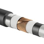
With cross-linked polyethylene insulation, for medium voltage 10, 20, 35 kV,
including flame-retardant "ng-LS", "ng-HF",
ultraviolet-resistant "UF", armored and non-armored
KUSIL medium-voltage cables are designed for the transmission and distribution of electrical energy in stationary installations, with a rated AC voltage of 10, 20, and 35 kV at a nominal frequency of 50 Hz for networks with a grounded or isolated neutral. The cables comply with the requirements of the international standard IEC 60502-2 for power cables.
Cables are intended for group or single installation in cable structures, ducts, industrial premises (including damp and frequently flooded areas), in the ground (including areas with high humidity), and in water (in non-navigable water bodies). Cables with the “UF” designation can be installed outdoors without protection from solar radiation. The cables are designed for routes without level difference restrictions. They can also be used in explosive zones in compliance with the requirements of GOST R IEC 60079-14-2008.
KUSIL cables according to TU 3500-024-76960731-2012 are manufactured as single-core and three-core (Table 1) with cross-linked polyethylene insulation. Armored cables are produced only in a three-core configuration.
The conductive cores of the cables are made of copper or aluminum, multi-wire, compacted, and comply with Class 2 according to GOST 22483-77.
The conductive cores of single-core cables for a rated voltage of 10 kV have a nominal cross-section of 35-1000 mm², and for a rated voltage of 20 and 35 kV — 50-1000 mm², as specified in Table 1.
The conductive cores of three-core cables for a rated voltage of 10 kV have a circular shape with a nominal cross-section of 35-300 mm² or a sector shape with a nominal cross-section of 120-300 mm², as specified in Table 1. The cores of three-core cables for a rated voltage of 20 and 35 kV have a circular shape with a nominal cross-section of 50-300 mm².
At the customer’s request, a numerical marking of the cores can be printed on the surface of the insulation screen of three-core cables.
All cables have a copper wire screen (Table 2), over which a copper tape is spirally applied.
Cables with longitudinal (“g”), longitudinal and transverse (“2g”) sheath sealing, as well as sealing of conductive cores (“zh”), can be used for installation in areas with high soil moisture, in damp and partially flooded premises, and in water (in non-navigable water bodies), provided that measures are taken to prevent mechanical damage to the cable.
Cables with a reinforced sheath (“u” — with longitudinal stiffening ribs) and armored cables (“B”) are used for installation on complex routes—those containing more than four bends at angles greater than 30° or straight sections with more than four transitions in pipes over 20 m in length, or with more than two pipe transitions exceeding 40 m in length. The armored cable (“B”) provides maximum protection for the conductive cores from external mechanical impacts due to the use of galvanized steel tapes and an additional sheath in its construction.
The outer sheath of cables marked with the sheath material designation “P” is made of polyethylene, allowing these cables to be installed in the ground regardless of soil corrosivity. The sheath of cables marked with the designation “V” is made of polyvinyl chloride (PVC) plastic compound—these cables are suitable for installation in dry soils (sandy-clay and normal soil with a moisture content of less than 14%).
Cables with fire safety ratings “ng(A)-LS” and “ng(B)-LS” have an outer sheath made of low-hazard PVC plastic compound (with reduced smoke and gas emissions). Cables with the “ng(A)-HF” rating have an outer sheath made of a halogen-free polymer composition—these cables do not emit corrosive gaseous byproducts when burning or smoldering. Cables with the “ng(A)-LS,” “ng(B)-LS,” or “ng(A)-HF” ratings can be used for group installations.
| Number of cores: 1; 3 |
| Nominal core cross-section (see Table 1) |
| “c” – sector-shaped core, only for 3-core cables with a voltage of 10 kV (see Table 1)1 |
| Cross-section of the copper screen (see Table 2) |
| Nominal voltage: 10; 20; 35kV |
| Core material1 | |
| copper | |
| A | aluminum |
| Insulation of cores made of cross-linked polyethylene |
| “B” – armor made of galvanized steel tapes (only for 3-core cables)1 |
| Sheath material | |
| V | PVC |
| P | polyethylene |
| “u” – reinforced polyethylene sheath with longitudinal stiffening ribs1,2,3 |
| Sheath sealing1 | |
| g | longitudinal |
| 2g | longitudinal and transverse |
| “zh” – longitudinal sealing of conductive cores, used together with longitudinal and transverse sheath sealing “2g”1,2 |
| Special cable characteristic1 | |
| HL | frost-resistant design (only for cables with a PVC sheath) |
| UF | resistance to solar radiation (only for cables with a polyethylene sheath) |
x
/
–
| Cable fire safety indicator1 | |
| ng(A)-LS | Category A for flame retardancy in group installations; with reduced smoke and gas emissions4 |
| ng(B)-LS | Category B for flame retardancy in group installations; with reduced smoke and gas emissions4 |
| ng(A)-HF | Category A for flame retardancy in group installations; does not emit corrosive gaseous products during combustion and smoldering2 |
1 — this field is not mandatory and is filled in if necessary
2 — only for cables with a polyethylene (P) sheath
3 — only for non-armored cables
4 — only for cables with a PVC (V) sheath
| Example of a designation entry when ordering | |
| KUSIL 3×150/25-35 PvPu2gzh TU 3500-024-76960731-2012 | Power cable with longitudinal sealing of three round copper conductors, in a reinforced polyethylene sheath with longitudinal and transverse sealing, with a cross-section of 150 mm², with a copper screen of 25 mm², for a voltage of 35 kV |
| Conductor | Nominal cross-section of the conductor, mm2 | |
| Single-core cables | Three-core cables | |
| Round | 35; 50; 70; 95; 120; 150; 185; 240; 300; 400; 500; 630; 800; 1000 | 35; 50; 70; 95; 120; 150; 185; 240; 300 |
| Sector-shaped | – | 120; 150; 185; 240; 300 |
| Nominal conductor cross-section, mm2 | Copper screen cross-section, mm2 not less than |
| 35-120 | 16 |
| 150-300 | 25 |
| More than 400 | 35 |
| Nominal voltage | AC voltage 10kV, 25kV, 35kV at 50 Hz frequency with grounded or isolated neutral | ||
| Operating temperature | — from -60°C to +50°C for cables with polyethylene (P) sheath — from -50°C to +50°C for cables with PVC (V) sheath — from -60°C to +50°C for frost-resistant cables (HL) | ||
| Minimum installation temperature (without preheating) | — not below -20°C for cables with polyethylene (P) sheath — not below -15°C for cables with PVC (V) sheath | ||
| Permissible continuous conductor heating temperature | 90°C | ||
| Maximum permissible temperature | Conductor heating during short circuit | 250°C | |
| Copper screen heating | 350°C | ||
| Conductor heating during short circuit under fire safety conditions | 400°C (short-circuit current up to 5s) | ||
| Permissible conductor heating in overload mode | < 130°C, duration not more than 8 hours per day and not more than 1000 hours over the service life | ||
| Electrical resistance of conductors to DC | meets the requirements of GOST 22483-77 | ||
| Climatic design | UHL and U, placement category 1 and 2 (according to GOST 15150-69), including installation in soil and water | ||
| Bending radius (D — outer cable diameter) | — at least 15D for single-core cables (7.5D allowed with a special template) — at least 10D for three-core cables | ||
| Warranty period | 5 years | ||
| Service life | at least 30 years | ||
| Nominal conductor cross-section, mm2 | Capacitance of 1 km of cable, µF | ||
| Nominal cable voltage, kV | |||
| 10 | 20 | 35 | |
| 35 | 0,22 | – | – |
| 50 | 0,25 | 0,17 | 0,14 |
| 70 | 0,29 | 0,19 | 0,16 |
| 95 | 0,32 | 0,21 | 0,18 |
| 120 | 0,35 | 0,23 | 0,19 |
| 150 | 0,38 | 0,26 | 0,20 |
| 185 | 0,42 | 0,27 | 0,22 |
| 240 | 0,46 | 0,29 | 0,24 |
| 300 | 0,51 | 0,32 | 0,26 |
| 400 | 0,57 | 0,35 | 0,29 |
| 500 | 0,63 | 0,39 | 0,32 |
| 630 | 0,70 | 0,43 | 0,35 |
| 800 | 0,77 | 0,49 | 0,40 |
| 1000 | 0,87 | 0,57 | 0,39 |
| Nominal conductor cross-section, mm2 | Cable currents (A) at 10 kV / 20 and 35 kV voltage when laid in the ground / in the air | |||||
| Single-core cables | Three-core cables | |||||
| With copper conductor depending on arrangement | With aluminum conductor depending on arrangement | Cable with copper conductors | Cable with aluminum conductors | |||
| In-plane | Triangular | In-plane | Triangular | |||
| 35 | 175 / – 217 / – | 181 / – 192 / – | 153 / – 189 / – | 145 / – 150 / – | 175 / – 173 / – | 136 / – 134 / – |
| 50 | 250 / 230 290 / 290 | 225 / 225 240 / 250 | 195 / 185 225 / 225 | 170 / 175 185 / 190 | 207 / 207 206 / 215 | 156 / 161 159 / 163 |
| 70 | 310 / 290 360 / 365 | 275 / 270 300 / 310 | 240 / 225 280 / 280 | 210 / 215 230 / 240 | 253 / 248 255 / 264 | 193 / 199 196 / 204 |
| 95 | 336 / 336 448 / 446 | 326 / 326 387 / 389 | 263 / 263 349 / 348 | 253 / 253 300 / 301 | 300 / 300 329 / 331 | 233 / 233 255 / 256 |
| 120 | 380 / 380 515 / 513 | 370 / 371 445 / 448 | 298 / 298 403 / 402 | 288 / 288 346 / 348 | 340 / 341 374 / 376 | 265 / 265 291 / 292 |
| 150 | 416 / 417 574 / 573 | 413 / 413 503 / 507 | 329 / 330 452 / 451 | 322 / 322 392 / 394 | 384 / 384 423 / 426 | 300 / 300 329 / 331 |
| 185 | 466 / 466 654 / 652 | 466 / 466 577 / 580 | 371 / 371 518 / 516 | 364 / 365 450 / 452 | 433 / 433 479 / 481 | 338 / 339 374 / 375 |
| 240 | 531 / 532 762 / 760 | 537 / 538 677 / 680 | 426 / 426 607 / 605 | 422 / 422 531 / 533 | 500 / 500 562 / 564 | 392 / 392 441 / 442 |
| 300 | 590 / 582 865 / 863 | 604 / 605 776 / 779 | 477 / 477 693 / 690 | 476 / 476 609 / 611 | 563 / 563 630 / 630 | 456 / 456 490 / 490 |
| 400 | 633 / 635 959 / 957 | 677 / 678 891 / 895 | 525 / 526 787 / 783 | 541 / 541 710 / 712 | ||
| 500 | 697 / 700 1081 / 1081 | 759 / 762 1025 / 1027 | 287 / 588 900 / 897 | 614 / 615 822 / 824 | ||
| 630 | 762 / 766 1213 / 1213 | 848 / 851 1166 / 1172 | 653 / 655 1026 / 1023 | 695 / 699 954 / 953 | ||
| 800 | 825 / 830 1349 / 1351 | 933 / 942 1319 / 1325 | 719 / 722 1161 / 1159 | 780 / 782 1094 / 1096 | ||
| 1000 | 900 / 906 1423 / 1430 | 1003 / 1007 1411 / 1415 | 800 / 805 1220 / 1230 | 845 / 850 1180 / 1186 | ||
| ||||||
| Clearance between cables, mm | Coefficients for the number of cables | |||||
| 1 | 2 | 3 | 4 | 5 | 6 | |
| 100 | 1,0 | 0,90 | 0,85 | 0,80 | 0,78 | 0,75 |
| 200 | 1,0 | 0,92 | 0,87 | 0,84 | 0,82 | 0,81 |
| 300 | 1,0 | 0,93 | 0,90 | 0,87 | 0,86 | 0,85 |
| Nominal conductor cross-section, mm2 | Permissible one-second short-circuit current of the cable, kA | |
| with copper conductor | with aluminum conductor | |
| 35 | 5,0 | 3,3 |
| 50 | 7,15 | 4,7 |
| 70 | 10,0 | 6,6 |
| 95 | 13,6 | 8,9 |
| 120 | 17,2 | 11,2 |
| 150 | 21,5 | 14,2 |
| 185 | 26,5 | 17,5 |
| 240 | 34,3 | 22,7 |
| 300 | 42,9 | 28,2 |
| 400 | 57,2 | 37,6 |
| 500 | 71,5 | 47,0 |
| 630 | 90,1 | 59,2 |
| 800 | 114,4 | 75,2 |
| 1000 | 142,9 | 94,5 |
| Nominal cross-section of the copper screen, mm2 | One-second short-circuit current, kA, not exceeding |
| 16 | 3,1 |
| 25 | 4,8 |
| 35 | 6,7 |
| 50 | 9,6 |
| 70 | 13,4 |
0 шт.
цена за шт. - 0 ₽

Error: Contact form not found.
Error: Contact form not found.


