
To find out the cost of the cable, send the order code to our managers.
Delivery is carried out as soon as possible after the order is placed.
control, management, installation, measuring
KUIN cables are designed for use in control, monitoring, and signaling circuits, inter-instrument connections, the formation of digital information buses, and as measuring wires for resistance thermometers (twisted pairs, triples, and quadruples for 2-wire, 3-wire, and 4-wire connection schemes). The cables can be used for data transmission in the frequency range up to 4 MHz, as well as for connecting AC electrical equipment with a nominal voltage of up to 690 V at a frequency of 50 or 60 Hz, or DC electrical equipment with a nominal voltage of up to 1000 V.
The cables can be installed in explosive hazardous areas of all classes (in accordance with the requirements of GOST IEC 60079-14-2013) and in open-air environments (in compliance with GOST R 50571.5.52-2011). They can also be used in metro infrastructure facilities and nuclear energy facilities in AS safety class 2, 3, and 4 systems according to NP-001-15 classification, outside the hermetic zone.
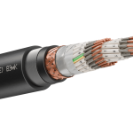
KUIN cables are manufactured with multi-stranded copper conductors or tinned “l” conductors (GOST 22483):
The nominal conductor cross-section and number of pairs are specified in Table 2. By agreement with the customer, cables can be manufactured with a different number of conductors and nominal cross-sections, as well as with a combined conductor cross-section.
In fire-resistant “FR” cables, a wrapping of two mica-containing tapes is applied over the current-carrying conductors, preventing short circuits between them in case of fire.
Conductor insulation can be made of the following materials:
The marking of insulated conductors is either color-coded or numerical (with numbers spaced no more than 35 mm apart).
Insulated conductors can be twisted into a common core, into pairs “x2”, triples “x3”, or quadruples “x4”.
Cables with a common conductor twist may include a grounding conductor “(PE)” in yellow-green color.
Each conductor (pair, triple, quadruple) can have an individual shield:
An insulating polymer film is applied over each individual shield, ensuring no electrical contact between adjacent shields. In individual shields “(E)”, “(Em)”, “(El)”, “(EEl)”, and “(Emf)”, instead of a film, an extruded layer of polymer material is applied, providing reliable insulation between the shields of pairs.
A water-blocking tape is applied over the cable core to prevent longitudinal moisture propagation in case of outer sheath damage.
A common shield of type “E”, “Em”, “El”, “EEl”, or “Emf” may be applied over the water-blocking tape.
An extruded separation layer is applied over the common shield or water-blocking tape, filling the free spaces between conductors (in accordance with GOST IEC 60079-14-2013). As a result, the cable cross-section becomes round, preventing an explosive gas mixture from migrating from a hazardous area to a safe one through a tightly sealed cable in case of sheath damage. Round-section cables can be used with any type of cable gland. By agreement with the customer, cables can be manufactured without extruded filling.
Cables (except single-core ones) can have armor made of galvanized steel wires in the form of a solid winding “K” or a braid “Ko”, or galvanized steel tapes “B”.
An outer sheath is applied over the armor. The cable sheath is made of PVC plastic compounds, halogen-free polymer compositions, or thermoplastic elastomers (see Table 3).
The cable sheath color is determined in the order code. If not specified, cables are manufactured in black.
“T” – increased heat resistance, operates at temperatures up to +200°C (only for material “T”),
“HL” – cold-resistant, cable installation without additional heating is possible down to -30°C,
“EHL” – resistant to extremely cold conditions, cable installation is possible down to -40°C,
“UF” – resistant to solar radiation, cables have placement category 1 according to GOST 15150: resistant to rain exposure, dynamic abrasive dust impact, and frost formation,
“H” – resistant to acids, alkalis, and environments with a high hydrogen sulfide content,
“M” – resistant to gasoline and industrial oil,
“ZG” – with a sheath resistant to rodents, ants, and termites. Such a cable has a fire hazard rating of ng(C)-HF or “ng(C)-FRHF.”
| Fire hazard rating |
| no index |
| ng(A) |
| ng(A)-LS |
| ng(A)-LSLTx |
| ng(A)-HF |
| ng(A)-FR |
| ng(A)-FRLS |
| ng(A)-FRLSLTx |
| ng(A)-FRHF |
| Individual shielding of each conductor (pair, triple, quadruple) | |
| without individual shielding | |
| E | aluminum foil tape (alumoflex) |
| Em | copper wire braid |
| El | tinned copper wire braid |
| EEl | tinned copper wire braid applied over alumoflex |
| Emf | copper foil tape |
| (E), (Em), (El), (EEl) | shields are insulated from each other by an extruded polymer layer |
| Conductor cross-section, mm² |
| 0.20 (no “FR”); 0.35; 0.50; 0.75; 1.0; 1.2; 1.5; 2.5; 4 (common twists); 6 (overall twisting) |
| Tinning of the conductor | |
| non-tinned conductor | |
| l | tinned conductor |
| Sheath and insulation material | |
| V | PVC plastic compound |
| P | halogen-free polymer compositions |
| Ps | cross-linked polyolefin insulation, sheath – PVC or halogen-free composition |
| T | thermoplastic elastomer |
x
–
TU 3581-010-76960731-2008
| High flexibility (conductor not lower than class 5) | |
| standard flexibility | |
| G | cable with high-flexibility conductors |
| Number of conductors (pairs, triples, quads) |
| 1…61 – number of conductors in the overall twist |
| 1…44 x 2 – number of pairs 1…44 |
| 1…24 x 3 – number of triples 1…24 |
| 1…14 x 4 – number of quads 1…14 |
| Presence of grounding conductor (only for cables with overall conductor twisting) | |
| without grounding conductor | |
| (PE) | grounding conductor |
| Overall shield over the core of all conductors | |
| without overall shield | |
| E | aluminum foil film (alumoflex) |
| Em | braid of copper wires |
| El | braid of tinned copper wires |
| EEI | braid of tinned copper wires applied over alumoflex |
| Emf | copper foil film |
| Armor under the outer sheath (except for single-core cables) | |
| without armor | |
| K | solid winding of galvanized wires under the outer sheath |
| Ko | braid of galvanized wires under the outer sheath |
| B | tape armor made of galvanized steel tapes |
| Special characteristics | |
| no special characteristic | |
| HL | increased frost resistance of cables |
| EHL | resistance to extreme cold conditions |
| UV | resistant to ultraviolet exposure throughout the cable’s service life, resistant to rain, dynamic abrasive dust impact, and frost deposition |
| M | oil and fuel resistance |
| H | resistance to chemically aggressive environments |
| T | increased heat resistance up to +200°C (only for material “T”) |
| ZG | sheath resistance to damage by rodents, ants, termites. Fire hazard rating “ng(C)-HF” or “ng(C)-FRHF” |
| c | cable with a blue-colored sheath |
| Example of cable designation when ordering | |
| KUIN ng(A)-LS 2x2x1.5L EmVK TU 3581-010-76960731-2008 | KUIN cable, flame-retardant, with low smoke and gas emission, with insulation and sheath made of PVC compounds with reduced fire hazard, with two pairs of tinned copper conductors with a nominal cross-section of 1.5 mm², each twisted pair has an individual shield in the form of a copper wire braid, under the outer sheath there is armor in the form of a solid winding of galvanized steel wires, the cable has extruded filling of the gaps between the conductors, the cable is round in cross-section, operating temperature from -50º to +70ºC, installation down to -15ºC |
| KUIN ng(A)-FR 5×1.0(PE) TEl TU 3581-010-76960731-2008 | KUIN cable, fire-resistant, flame-retardant, with insulation and sheath made of thermoplastic elastomers, with an overall shield in the form of a tinned copper wire braid, without armor, with five copper conductors with a nominal cross-section of 1.0 mm² in a common twist, one of the conductors is a ground wire (PE) of yellow-green color, the cable has extruded filling of the gaps between the conductors, the cable is round in cross-section, operating temperature from -60º to +125ºC, installation down to -30ºC |
| KUIN ng(A)-HF 5x3x0.75L EPE-EHL TU 3581-010-76960731-2008 | KUIN cable, flame-retardant, with insulation and sheath made of halogen-free polymer compositions, with five triples of tinned copper conductors with a nominal cross-section of 0.75 mm², individual shields of the twisted triples and the overall shield are made of aluminum foil tape with a multi-wire tinned drain conductor, the cable is without armor, it has extruded filling of the gaps between the conductors, the cable is round in cross-section, resistant to extremely cold conditions, operating temperature from -70º to +70ºC, installation down to -40ºC |
| Rated Voltage | – up to 690 V AC at standard frequency 50 or 60 Hz – up to 1000 V DC | |
| Electrical insulation resistance at +20°C, not less than | – 500 MΩ/km for cross-linked polyolefin insulation – 100 MΩ/km for halogen-free polymer compositions and thermoplastic elastomer – 10 MΩ/km for PVC insulation | |
| Electrical resistance of conductive cores (at +20°C) | Electrical resistance of cores with a cross-section of 0.2-1.0 mm2and 1.5-6.0 mm2complies with GOST 22483-2012. Electrical resistance of conductive core with a nominal cross-section of 1.2 mm², not more than: – Class 3 core: tinned core – 17.6 Ω/km, untinned core – 17.3 Ω/km, – Class 4 and 5: tinned core – 16.5 Ω/km, untinned core – 16.0 Ω/km | |
| Cable test with AC voltage at 50 Hz for 5 min | Unshielded cables: – 2500 V (for cores 0.35-6 mm2) – 2000 V (for cores 0.2 mm2) Shielded cables: – 2000 V (for cores 0.35-6 mm2) – 1500 V (for cores 0.2 mm2) | |
| Maximum capacitance | At 1.0 kHz frequency, recalculated per 1 km length at +20°C, not more than | Between adjacent cores: – 70 nF (for cores 0.2-0.75 mm2) and 100 nF (for cores 1.0-6.0 mm2) for cables with “Ps” material – 140 nF (for cores 0.2-0.75 mm2) and 180 nF (for cores 1.0-6.0 mm2) for cables with “V”, “P”, “T” material Between a core connected to the shield and another arbitrary core: – 180 nF for cables with “Ps” material – 300 nF for cables with “V”, “P”, “T” material |
| Maximum inductance | 0.9 mH | |
| Operating temperature in a stationary state | -60° to +70°C for cables with “HL” index (up to +80°C with “Ps” material) -70° to +70°C for cables with “EHL” index (up to +80°C with “Ps” material) -60° to +125°C for cables with “T” material -50° to +200°C for cables with “T” material and “T” index (high heat resistance) -50° to +70°C for other cable types (up to +80°C with “Ps” material) | |
| Minimum installation temperature, not below | – minus 40°C for cables with “EHL” index – minus 30°C for cables with “HL” index or “T” material – minus 15°C for other cable types | |
| Impact resistance at low temperatures | down to -60°C for “EHL” cables, down to -40°C for “HL” cables | |
| Climatic design according to GOST 15150 | Design “B” placement category 1-5, suitable for all macroclimatic regions | |
| Fire resistance of cables with “FR” index | At least 180 minutes under flame exposure and temperature of at least +750°C (PO1 according to GOST 31565) | |
| Resistance to longitudinal moisture penetration under the sheath | Fully blocked at a distance of 0.5 m from penetration point (special water-blocking tape applied in all cables) | |
| Mold resistance | Cables resistant to mold exposure, biological fouling degree up to 2 points | |
| Seismic and vibration resistance | Maintains operability under seismic impact of at least 7 points on the MSK-64 scale. | |
| Resistance to decontaminating solution | Resistant, solution composition according to clause 6.5.9 of PNST 167-2016 or as agreed | |
| Permissible bending radii for installation and operation in D (outer cable diameter), not less than | – 3D for non-armored cables – 4D for wire-armored cables – 5D for tape-armored cables | |
| Cable service life, not less than | For cables with thermoplastic elastomer insulation and sheath – at least 25 years, other cables – at least 30 years | |
| Warranty period | 2 years from commissioning date | |
| Structural element | Nominal conductor cross-section, mm2 | Number of conductors, pairs, triples, quadruples |
| Conductor | 0.20; 0.35; 0.50; 0.75; 1.0; 1.2; 1.5; 2.5; 4; 6 | 1, 2, 3, 4, 5, 6, 7, 8, 9, 10, 11, 12, 13, 14, 15, 16, 18, 19, 20, 21, 22, 24, 27, 30, 37, 40, 44, 48, 52, 61 |
| Pair (×2) | 0.20; 0.35; 0.50; 0.75; 1.0; 1.2; 1.5; 2.5 | 1, 2, 3, 4, 5, 6, 7, 8, 9, 10, 11, 12, 13, 14, 15, 16, 18, 19, 20, 21, 22, 24, 27, 30, 37, 40, 44 |
| Triple (×3) | 1, 2, 3, 4, 5, 6, 7, 8, 9, 10, 11, 12, 13, 14, 15, 16, 18, 19, 20, 21, 22, 24 | |
| Quadruple (×4) | 1, 2, 3, 4, 5, 6, 7, 8, 9, 10, 11, 12, 13, 14 |
* – By agreement with the customer, cables can be manufactured with a different number and nominal cross-section of conductors (pairs, triples, quadruples).
– Cables with conductors of a nominal cross-section of 0.20 mm² are not manufactured in the fire-resistant “FR” version.
| Designation of sheath and insulation material | Fire hazard rating | Description of sheath and insulation material, as well as cable type according to fire hazard rating (as per GOST 31565-2012) |
| V | –(no index) | cables with insulation and sheath made of PVC plastic compounds, not propagating combustion in single installation |
| ng(A) | cables with PVC plastic insulation and low-flammability PVC plastic sheath, not propagating combustion in group installation under category A | |
| ng(A)-LS | cables with insulation and sheath made of low-fire-hazard PVC plastics, not propagating combustion in group installation under category A, with reduced smoke and gas emission | |
| ng(A)-LSLTx | cables with insulation and sheath made of low-fire-hazard PVC plastics, not propagating combustion in group installation under category A, with reduced smoke and gas emission, and low toxicity of combustion products | |
| ng(A)-FRLS | fire-resistant cables with insulation and sheath made of low-fire-hazard PVC plastics, not propagating combustion in group installation under category A, with reduced smoke and gas emission | |
| ng(A)-FRLSLTx | fire-resistant cables with insulation and sheath made of low-fire-hazard PVC plastics, not propagating combustion in group installation under category A, with reduced smoke and gas emission, and low toxicity of combustion products | |
| P | ng(A)-HF | cables with insulation and sheath made of halogen-free polymeric compounds, not propagating combustion in group installation under category A, and not emitting corrosive gaseous combustion products |
| ng(A)-FRHF | fire-resistant cables with insulation and sheath made of halogen-free polymeric compounds, not propagating combustion in group installation under category A, and not emitting corrosive gaseous combustion products | |
| Ps | ng(A)-LS | cables with cross-linked polyolefin insulation and low-fire-hazard PVC sheath, not propagating combustion in group installation under category A, with reduced smoke and gas emission |
| ng(A)-FRLS | fire-resistant cables with cross-linked polyolefin insulation and low-fire-hazard PVC sheath, not propagating combustion in group installation under category A, with reduced smoke and gas emission | |
| ng(A)-HF | cables with cross-linked polyolefin insulation and a halogen-free polymer sheath, not propagating combustion in group installation under category A, and not emitting corrosive gaseous combustion products | |
| ng(A)-FRHF | fire-resistant cables with cross-linked polyolefin insulation and a halogen-free polymer sheath, not propagating combustion in group installation under category A, and not emitting corrosive gaseous combustion products | |
| T | ng(A) | cables with insulation and sheath made of thermoplastic elastomers, not propagating combustion in group installation under category A |
| ng(A)-FR | fire-resistant cables with insulation and sheath made of thermoplastic elastomers, not propagating combustion in group installation under category A |
* – “ZG” cable (rodent-resistant) is made of material “P” with rating “ng(S)-HF” or “ng(S)-FRHF”
| Insulation and sheath material | Permissible conductor heating temperature, ºC | |||
| long-term permissible | under overload conditions | maximum during short circuit | non-ignition during short circuit | |
| “V” – PVC plastic compound | 70 | 90 | 160 | 350 |
| “P” – halogen-free polymer composition | ||||
| “Ps” – cross-linked polyolefin | 90 | 130 | 250 | 400 |
| “T” – thermoplastic elastomer | 125 | 150 | 200 | 350 |
0 шт.
цена за шт. - 0 ₽

Error: Contact form not found.
Error: Contact form not found.


