
To find out the cost of the cable, send the order code to our managers.
Delivery is carried out as soon as possible after the order is placed.
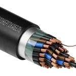
Flexible cables of the KGVV, KGVVng(A) (non-armored), KGVVE, KGVEV (overall shielded), and KGVBbV (tape-armored) brands are designed for the transmission and distribution of electrical energy in power circuits (660 V and 1000 V) and control and monitoring circuits of machines and mechanisms at voltages up to 660 V AC with a frequency of up to 60 Hz or up to 1000 V DC, used for non-stationary installation.
Cables can also be used for fixed installation of power and control circuits in machines and mechanisms. For stationary installation, a bending radius of at least five times the outer diameter of the cable must be maintained.
Fire-resistant flexible cables (with the “FR” index) can be used for installation in fire protection systems. They are suitable for electrical wiring in hospital operating rooms, emergency power supply circuits, and equipment power systems that must function during a fire.
Cable construction
The copper multi-wire conductive core of a round shape complies with the requirements of GOST 22483 (KG – class 4, KPG – class 5).
By agreement with the customer, cables with a different number of conductors can be manufactured.
In fire-resistant "FR" cables, a wrapping of two mica-containing tapes is applied over the conductive cores, preventing short circuits between the conductors in case of fire.
| Cable brand | Nominal conductor cross-section, mm² | ||||||||
| 0.5 | 0.75 | 1 | 1.5 | 2.5 | 4-6 | 10 | 16-50 | 70-240 | |
| Number of conductors in the cable | |||||||||
| KGVV, KGVVE, KGVVng(A), KGVVEng(A) | 2-5; 7; 10; 14; 19; 24; 27; 30; 37; 48; 52; 61 | 2-5; 7; 10; 14; 19; 24; 27; 37 | 2-5; 7; 10 | – | – | – | |||
| KGVEV, KGVEVng(A)-LS, KGVVng(A)-LS | – | 2-7; 10; 12; 14; 19; 27; 37; 48; 52; 61 | 2-5; 7 | 1-5 | |||||
| KPGVV, KPGVVng(A)-LS, KPGVVng(A)-FRLS | – | – | – | 1-5 | – | – | – | – | |
| KGVVng(A)-FRLS, KGVEVng(A)-FRLS | 3-5; 7; 10; 14; 19; 24; 27; 30; 37; 48; 52; 61 | 7; 10; 14; 19; 24; 27; 30; 37; 48; 52; 61 | 1-5; 7; 10; 19; 24; 27; 30; 37; 48; 52; 61 | 1-5; 7 | 1-5 | – | |||
The conductive cores of single-core and multi-core cables of all cross-sections must be of a round shape.
Three-core, four-core, and five-core cables may have all conductors of the same cross-section or one conductor of a smaller cross-section (grounding or neutral conductor).
| Conductor designation | Nominal conductor cross-section, mm² | ||||||||||||||
| Main | 1.5 | 2.5 | 4 | 6 | 10 | 16 | 25 | 35 | 50 | 70 | 95 | 120 | 150 | 185 | 240 |
| Neutral conductor | 1.5 | 1.5 | 2.5 | 4 | 6 | 10 | 16 | 16 | 25 | 35 | 50 | 70 | 70 | 95 | 120 |
| Grounding conductor | 1.0 | 1.5 | 2.5 | 2.5 | 4 | 6 | 10 | 16 | 16 | 25 | 35 | 35 | 50 | 50 | 70 |
The conductor insulation can be made from the following material:
“V” – polyvinyl chloride plastic compound, including low-flammability and low-fire-hazard types.
The conductor insulation is extruded, tightly adhering to the conductors, without foreign inclusions. The outer surface of the insulation is free from dents, bubbles, and cracks that would cause the insulation thickness to exceed permissible deviations. The insulation of fire-resistant cables is applied over a thermal barrier made of mica-containing tapes.
The insulation of single-core cables can be of any color. The conductor coloring is either solid (ring-shaped) or in the form of two longitudinal (diametrically positioned) stripes at least 1 mm wide.
In cables with more than 5 conductors, numbering is used (the distance between the numbers is no more than 50 mm), starting from "zero".
The insulation of the neutral conductor is blue (N). The insulation of the grounding conductor is two-colored (green-yellow) (PE).
| Number of conductors in the cable, pcs | Insulation color of conductors | ||||
| Conductor sequence number | |||||
| 1 | 2 | 3 | 4 | 5 | |
| 2 | Brown | Blue | – | – | – |
| 3 | Gray | Brown | Black | – | – |
| Brown | Blue | Green-yellow | – | – | |
| 4 | Gray | Brown | Black | Blue | – |
| Gray | Brown | Black | Green-yellow | – | |
| 5 | Gray | Brown | Black | Blue | Green-yellow |
| Gray | Brown | Black | Blue | Black | |
The insulated conductors are twisted into a core with concentric layers, with a twisting pitch not exceeding: for KG – 20 Dsk, for KPG – 16 Dsk, where Dsk is the diameter of the circle described around the twisted conductors.
A polyethylene terephthalate (PET) tape is applied over the twisted conductors of all cable brands. The production of cables without a PET tape over the twisted conductors is allowed, provided that the mobility of the conductors is maintained and the sheath can be easily separated from the insulation when stripping the cable.
The inner sheath is made of polyvinyl chloride (PVC) plastic compound or low-fire-hazard PVC plastic compound.
It is allowed to use a wrapping of plastic film or another equivalent material instead of the inner sheath.
The inner sheath must not fuse with the insulation and should be removable without damaging the insulation when stripping the cable.
Shield:
“E” – a shield in the form of a wrapping made of aluminum (aluminum-polymer) or copper foil. The outer sheath “V” is applied over the shield, depending on the cable sheath material.
In the absence of specific instructions in the order, cables are manufactured with a black sheath.
Manufacturing of cables as agreed with the customer:
- with a different number and nominal cross-section of conductors;
- with a different class of conductive conductors;
- with a colored outer sheath (red, white, blue, or other colors);
- with flexible conductors made of aluminum alloy;
- with a protective layer in the form of armor made of two steel tapes.
| Sheath material designation | Fire hazard indicator | Description of the sheath material, cable type according to the fire hazard indicator (as per GOST 31565-2012) |
| V | (no index) | Sheath made of PVC compounds, does not propagate fire during single installation |
| ng(A) | Sheath made of low-combustibility PVC compound, does not propagate fire during group installation under category A | |
| ng(A)-LS | Sheath made of low-fire-hazard PVC compound, does not propagate fire during group installation under category A, with reduced smoke and gas emission | |
| ng(A)-FRLS | Fire-resistant cables with a sheath made of low-fire-hazard PVC compound, does not propagate fire during group installation under category A, with reduced smoke and gas emission |
| Name | Specifications |
| Nominal voltage | – AC voltage with a nominal frequency of 50 Hz: 660 V; 1000 V – AC voltage up to 660 V with a frequency of 60 Hz or DC voltage up to 1000 V |
| Electrical insulation resistance in operation, recalculated per 1 km length at t=+20 °C, not less than | – 12 MΩ for PVC insulation with a cross-section of 0.5÷1.5 mm²; – 10 MΩ for PVC insulation with a cross-section of 2.5÷4.0 mm²; – 9 MΩ for PVC insulation with a cross-section of 6.0 mm²; – 7 MΩ for PVC insulation with a cross-section of 10÷240 mm². |
| Electrical resistance of conductive cores at t=+20 °C, not more than | complies with GOST 22483-2021 |
| Testing of cables with AC voltage at 50 Hz (10 min): | – 3000 V for cables with a nominal voltage of 660 V; – 4000 V for cables with a nominal voltage of 1000 V. |
| Ambient temperature, upper limit | +50 °C |
| Ambient temperature, lower limit | -50 °C |
| Installation temperature, not lower than | -15 °C |
| Maximum operating temperature of the conductor | +70 °C |
| Maximum temperature of conductive cores of fire-resistant cables under non-ignition conditions during a short circuit | +400 °C |
| Minimum allowable bending radius of cables | 7.5 times the calculated outer cable diameter |
| Service life of cables, not less than | 12 years |
| Warranty period of operation, not less than | 3 years |
0 шт.
цена за шт. - 0 ₽

Error: Contact form not found.
Error: Contact form not found.


