
To find out the cost of the cable, send the order code to our managers.
Delivery is carried out as soon as possible after the order is placed.
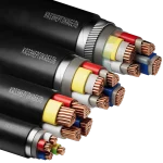
Power cables with plastic insulation of the following brands: VVG (unarmored), VVGE (with overall screen), VBShv (with tape armor), and VKShv (with wire armor made of steel wires) are designed for transmission and distribution of electric power in stationary installations at a nominal AC voltage of 0.66 and 1 kV with a nominal frequency of 50 Hz.
Cables can be used for single laying in dry and damp industrial premises, on special cable overpasses, in blocks, as well as for outdoor installation. They can also be used for group laying in the ground (trenches), premises, tunnels, ducts,
mines, and in open air, provided the cable is not subjected to significant tensile forces. However, if there is a risk of mechanical damage during operation, they can be used in fire protection systems that must function under fire conditions.
For electrical wiring in residential and public buildings, fire-resistant cables that do not propagate combustion during group laying, with reduced smoke and gas emission and low toxicity of combustion products, are recommended.
The main characteristics of the cables are provided in Table 6.
| Conductor name | Nominal conductor cross-section, mm² | |
| Round | Sector (Segmental) | |
| Single-wire conductors | 1.5 – 10 | – |
| Stranded conductors | 1.5 – 1000 | 70 – 300 |
Cables are manufactured with single-wire or stranded copper conductors of round or sector (segmental) shape, class 1 or 2 according to GOST 22483 (Table 1).
Shape of conductive cores:
– Round shape – used in single-core cables of all cross-sections and multi-core cables with cores of nominal cross-section up to 300 mm².
– Sector shape – used in 3-core, 4-core, and 5-core cables with core cross-sections of 70 mm² and above.
| Number of cores | Nominal cross-section of main cores, mm² | |
| Nominal voltage, kV | ||
| 0.66 | 1 | |
| 1, 2, 3, 4, and 5 | 1.5 – 50 | 1.5 – 240 |
| 1, 2, 3, and 4 | 1.5 – 50 | 1.5 – 400 |
| 1 | 1.5 – 50 | 1.5 – 1000 |
Multi-core cables have all cores of equal cross-section. Four-core and five-core cables may have one core of a smaller cross-section (neutral (N) or grounding (PE)) in accordance with Table 3. The smaller cross-section conductive core can be round or sector-shaped, single-wire or stranded compacted, depending on the class of the main cores in the cable.
By agreement with the customer, cables with a different number of cores can be manufactured.
| Core designation | Nominal cross-section, mm² | ||||||||||||||||
| Main | 1.5 | 2.5 | 4 | 6 | 10 | 16 | 25 | 35 | 50 | 70 | 95 | 120 | 150 | 185 | 240 | 300 | 400 |
| Neutral or grounding | 1.5 | 1.5 | 2.5 | 4 | 6 | 10 | 16 | 16 | 25 | 35 | 50 | 70 | 70 | 95 | 120 | 150 | 185 |
In fire-resistant “FR” cables, a winding of two mica-containing tapes is applied over the conductive cores, preventing them from short-circuiting during a fire.
The core insulation can be made of the following materials:
– “V” – polyvinyl chloride (PVC) plastic, including low-flammability and low-fire-hazard types.
– “P” – polyethylene plastic.
– “Pv” – cross-linked polyethylene (XLPE) plastic.
The insulation of single-core cables can be of any color. The coloring should be either solid or in the form of a longitudinal stripe at least 1 mm wide.
By agreement with the customer, other color combinations for the insulation of main cores are allowed.
| Number of cores in the cable, pcs | Core insulation color | ||||
| Core sequence number | |||||
| 1 | 2 | 3 | 4 | 5 | |
| 2 | gray* | blue | – | – | – |
| 3 | gray* | brown | black | – | – |
| gray* | blue | green-yellow | – | – | |
| 4 | gray* | brown | black | blue | – |
| gray* | brown | black | green-black** | – | |
| 5 | gray* | brown | black | blue | green-yellow |
| *or natural **by agreement with the customer | |||||
The insulation of the neutral core (N) must be blue. The insulation of the grounding core (PE) must be two-colored – green-yellow. By agreement with the customer, the main insulated cores may be marked with numbers starting from one.
The insulated cores must be twisted into a common core. The production of two-core and three-core flat cables (“-P”) with conductive cores of up to 16 mm² inclusive is allowed.
A polyethylene terephthalate (PET) film tape must be applied over the twisted cores of all cable types. The production of cables without a tape over the twisted cores is allowed, provided that the mobility of the cores is maintained and the sheath can be freely separated from the insulation when stripping the cables.
The belt insulation (padding) must be extruded from insulation material or polyvinyl chloride (PVC) plastic, or applied as a wrapping or longitudinally with tapes made of polyethylene terephthalate (PET) film, non-woven fabric, PVC plastic, or another equivalent material. In low-flammability or low-fire-hazard cables, the belt insulation (inner extruded sheath) is made of fire-resistant PVC plastic, which must fill all gaps between the cores.
Shielding and protective armor:
– “E” – a shield in the form of a winding made of copper wires.
– “B” – armor made of two steel tapes.
– “K” – armor made of galvanized steel wires.
A protective outer sheath (protective hose) – “Shv” or “Shp,” depending on the cable sheath material, is applied over the armor.
If no specifications are provided in the order, cables are manufactured with a black sheath.
Manufacturing of cables upon agreement with the customer:
with length marking on the cable sheath;
with a different number and nominal cross-section of conductors;
with a different flexibility class of conductive cores;
with a colored outer sheath (red, white, blue, or other colors).
| Sheath material designation | Fire hazard rating | Description of sheath material, cable type according to fire hazard rating (per GOST 31565-2012) |
| VG | (no index) | Sheath made of PVC plastic, does not propagate combustion in single installation |
| V | ng(A) | Sheath made of low-flammability PVC plastic, does not propagate combustion in group installation, category A |
| ng(A)-LS | Sheath made of low fire hazard PVC plastic, does not propagate combustion in group installation, category A, with reduced smoke and gas emission | |
| ng(A)-LSLTx | Sheath made of low fire hazard PVC plastic, does not propagate combustion in group installation, category A, with reduced smoke and gas emission, with low toxicity of combustion products | |
| ng(A)-FRLS | Fire-resistant cables with a sheath made of low fire hazard PVC plastic, do not propagate combustion in group installation, category A, with reduced smoke and gas emission | |
| ng(A)-FRLSLTx | Fire-resistant cables with a sheath made of low fire hazard PVC plastic, do not propagate combustion in group installation, category A, with reduced smoke and gas emission, with low toxicity of combustion products |
| Name | Specifications |
| Nominal voltage | AC voltage with a nominal frequency of 50 Hz: 0.66 kV; 1 kV |
| Electrical insulation resistance during operation, recalculated per 1 km length at t=+20 °C, not less than | – 150 MΩ for polyethylene insulation; – 12 MΩ for PVC insulation with a cross-section of 1.5 mm²; – 10 MΩ for PVC insulation with a cross-section of 2.5÷4.0 mm²; – 9 MΩ for PVC insulation with a cross-section of 6.0÷10.0 mm²; – 7 MΩ for PVC insulation with a cross-section of 10 mm² and above. |
| Electrical resistance of conductive cores at t=+20 °C, not less than | Complies with GOST 22483-2021 |
| Cable testing with AC voltage at 50 Hz (5 min) | 3000 V for cables with a nominal voltage of 0.66 kV; 3500 V for cables with a nominal voltage of 1.0 kV |
| Ambient temperature, upper limit | +50 °C |
| Ambient temperature, lower limit | -50 °C |
| Installation temperature, not below | -15 °C |
| Maximum operating temperature of the conductor | +70 °C |
| Fire resistance of cables with the “FR” index | At least 180 minutes under flame exposure and a temperature of at least +750 °C |
| Minimum allowable bending radius for installation and operation: | – for single-core cables – 10 times the calculated outer diameter of the cable; – for multi-core cables – 7.5 times the calculated outer diameter of the cable |
| Minimum service life | 30 years |
| Warranty period, not less than | 5 years from the date of cable commissioning |
| Nominal conductor cross-section, mm² | Permissible current loads for cables with PE and PVC insulation, A* | |||||
| Single-core** | Two-core | Three-core*** | ||||
| In air | In soil | In air | In soil | In air | In soil | |
| 1,5 | 29 | 32 | 24 | 33 | 21 | 28 |
| 2,5 | 40 | 42 | 33 | 44 | 28 | 37 |
| 4 | 53 | 54 | 44 | 56 | 27 | 48 |
| 6 | 67 | 67 | 56 | 71 | 49 | 58 |
| 10 | 91 | 89 | 76 | 94 | 66 | 77 |
| 16 | 121 | 116 | 101 | 123 | 87 | 100 |
| 25 | 160 | 148 | 134 | 157 | 115 | 130 |
| 35 | 197 | 178 | 166 | 190 | 141 | 158 |
| 50 | 247 | 217 | 208 | 230 | 177 | 192 |
| 70 | 318 | 265 | – | – | 226 | 237 |
| 95 | 386 | 314 | – | – | 274 | 280 |
| 120 | 450 | 358 | – | – | 321 | 321 |
| 150 | 521 | 406 | – | – | 370 | 363 |
| 185 | 594 | 455 | – | – | 421 | 406 |
| 240 | 704 | 525 | – | – | 499 | 468 |
| * To determine the current loads for cables with vulcanized PE insulation when installed in air and in soil, these loads should be multiplied by factors of 1.16 and 1.13, respectively. For cables installed in water, the loads for soil installation should be multiplied by a factor of 1.3. ** The current loads are given for operation on direct current. *** Also applicable to four-core cables with a reduced-section neutral conductor. To determine the current loads of four-core cables with equal-section conductors in four-wire networks, when all conductors carry load in normal operation, these loads should be multiplied by a factor of 0.93. | ||||||
0 шт.
цена за шт. - 0 ₽

Error: Contact form not found.
Error: Contact form not found.


