
To find out the cost of the cable, send the order code to our managers.
Delivery is carried out as soon as possible after the order is placed.
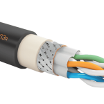
KVIP cables are designed for data transmission in measuring, control, and regulatory equipment within a frequency range of up to 16 MHz. They are used for forming digital information buses, connecting sensors with digitally frequency-modulated signals via RS-485, RS-482, RS-422 interfaces, and in systems such as Foundation Fieldbus, PROFIBUS, HART, and others that require the use of twisted pair as a data transmission channel.
The cables are also intended for connection to stationary electrical instruments, devices, and assemblies of electrical distribution equipment with voltages up to 690 V AC at 50 or 60 Hz or up to 1000 V DC.
The cables can be laid in hazardous areas of all classes (in compliance with the requirements of GOST IEC 60079-14-2013) and in open air (in accordance with the requirements of GOST R 50571.5.52-2011). They can also be used in metro facilities.
KVIP cables are manufactured with tinned or untinned copper “m” conductors, either single-wire or multi-wire, class 4 according to GOST 22483-2012.
The nominal cross-section of multi-wire conductors, the diameter of single-wire conductors, and the number of twisted pairs are specified in Table 2. By agreement with the customer, cables can be manufactured with a different number of twisted pairs, nominal conductor cross-section/diameter, as well as with combined conductor cross-sections in twisted pairs.
In fire-resistant “FR” cables, a wrapping of two mica-containing tapes is applied over the conductive cores, preventing short circuits between them in case of fire.
The conductor insulation is made of cross-linked polyolefin. The marking of insulated conductors is either color-coded or numeric (with numbers placed no more than 35 mm apart).
The insulated conductors are twisted into pairs with a pitch of no more than 40 mm, and in fire-resistant cables, no more than 60 mm. By agreement, the cable can be manufactured with an unequal and non-multiple twisting pitch of the twisted pairs.
Each twisted pair can have an individual shield:
An insulating polymer film is applied over each individual shield, eliminating electrical contact between adjacent shields. In individual shields of types “(E)”, “(Em)”, “(El)”, and “(EEl)”, instead of film, an extruded layer of polymer material is applied, providing reliable insulation between the shields.
A water-blocking tape is applied over the cable core to prevent longitudinal moisture penetration in case of outer sheath damage.
Over the water-blocking tape wrapping, a common shield of type “E”, “Em”, “El”, or “EEl” can be applied.
An extruded separation layer is applied over the common shield or water-blocking tape, filling the free spaces between the conductors (in accordance with GOST IEC 60079-14-2013). As a result, the cable takes a round cross-section, and in the event of sheath damage, an explosive gas mixture cannot travel along the compacted cable from a hazardous area to a safe one where non-explosion-proof equipment is used. A cable with a round cross-section can be used with any type of cable glands. By agreement with the customer, cables can be manufactured without extruded filling.
Cables can have armor made of galvanized wires:
The cable sheath is made of material (Table 3):
The sheath color is specified in the order code; if not specified, the cables are manufactured in black.
| Fire hazard rating |
| no index |
| ng(A) |
| ng(A)-LS |
| ng(A)-HF |
| ng(A)-FR |
| ng(A)-FRLS |
| ng(A)-FRHF |
| Number of twisted pairs |
| 1, 2, 3, 4, 5, 6, 7, 8, 9, 10, 11, 12, 13, 14, 15, 16, 17, 18, 19, 20, 21, 22, 23, 24, 25, 27, 30, 37, 40, 44 |
| Conductor tinning | |
| tinned conductor | |
| m | untinned conductor |
| Individual shielding of each pair | |
| without individual shielding | |
| E | aluminum foil film (alumoflex) |
| Em | braid of copper wires |
| El | braid of tinned copper wires |
| EEI | a braid of tinned copper wires applied over alumoflex |
| (E), (Em), (El), (EEl) | shields are insulated from each other by an extruded polymer layer; individual shields E, Em, El, EEl are insulated from each other by a polymer film (there is no electrical contact between the shields) |
| Sheath material, insulation – cross-linked polyolefin | |
| V | PVC plasticate |
| P | halogen-free polymer compositions |
| T | thermoplastic elastomer |
x 2 x
–
| Conductors |
| Cross-section of stranded conductors, mm²: 0.12; 0.20; 0.35; 0.5; 0.75; 1.0; 1.2; 1.5 |
| Diameter of solid conductors, mm: 0.40; 0.51; 0.64; 0.80 |
| Overall shield over the core of all twisted pairs | |
| without overall shield | |
| E | aluminum foil film (alumoflex) |
| Em | braid of copper wires |
| El | braid of tinned copper wires |
| EEl | a braid of tinned copper wires applied over alumoflex |
| Armor of galvanized steel wires | |
| without armor | |
| K | in the form of a continuous wire helix under the outer sheath |
| KG | in the form of a wire braid over the inner sheath, the outer sheath is not applied over the armor (“bare” armor) |
| Special characteristics | |
| without special characteristic | |
| HL | increased cold resistance of cables |
| EHL | resistance to extreme cold conditions |
| UF | resistance to ultraviolet exposure throughout the cable’s service life, resistance to rain, dynamic abrasive dust impact, and frost formation |
| M | oil and fuel resistance |
| H | resistance to chemically aggressive environments |
| T | increased heat resistance up to +200°C (only for material “T”) |
| ZG | sheath resistance to damage by rodents, ants, termites. Fire hazard rating “ng(C)-HF” or “ng(C)-FRHF” |
| s | cable with a blue-colored sheath |
| Example of cable designation when ordering | Description |
| KVIP ng(A)-LS 2x2x1.5 EmVK TU 3581-012-76960731-2008 | High-speed data transmission cable, flame-retardant, with low smoke and gas emission, insulated with cross-linked polyolefin and sheathed with low fire hazard PVC plasticates, with two twisted pairs of tinned copper conductors with a nominal cross-section of 1.5 mm², each pair has an individual shield in the form of a braid of copper wires, under the outer sheath there is armor made of galvanized steel wires, the cable has extruded filling between the conductors, round in cross-section, operating temperature from -50º to +80ºC, installation down to -15ºC. |
| KVIP ng(A)-FR 5x2x0.51m TEl TU 3581-012-76960731-2008 | High-speed data transmission cable, fire-resistant, flame-retardant, insulated with cross-linked polyolefin and sheathed with thermoplastic elastomer, with an overall shield in the form of a braid of tinned copper wires, without armor, with five twisted pairs of solid copper conductors with a nominal diameter of 0.51 mm, the cable has extruded filling between the conductors, round in cross-section, operating temperature from -60º to +125ºC, installation down to -30ºC. |
| KVIP ng(A)-HF 5x2x0.75 EPE-EHL TU 3581-012-76960731-2008 | High-speed data transmission cable, flame-retardant, insulated with cross-linked polyolefin and sheathed with halogen-free polymer compositions, with five twisted pairs of tinned copper conductors with a nominal cross-section of 0.75 mm², individual shields for the twisted pairs and an overall shield made of aluminum foil laminate with a stranded tinned drain wire, the cable is unarmored, has extruded filling between the conductors, round in cross-section, resistant to extreme cold conditions, operating temperature from -70º to +80ºC, installation down to -40ºC. |
| Nominal Voltage |
– up to 690 V AC at a standard frequency of 50 or 60 Hz – up to 1000 V DC |
| Insulation resistance of conductors at t° = +20°C | at least 5000 MΩ/km |
| DC resistance of 1 km of conductive core at t° = +20°C |
|
| Voltage test for cables at 50 Hz AC |
2000 V – between conductors of unshielded cables 1500 V – between conductors and shield in shielded cables 500 V – between adjacent shields in shielded cables |
| Maximum capacitance | see Table 4 |
| Maximum inductance at t° = +20°C | not more than 0.9 mH/km at 1.0 kHz |
| Ohmic asymmetry of conductors in a pair | not more than 3% |
| Attenuation coefficient and characteristic impedance | see Table 5 |
| Pair capacitance asymmetry at 0.8 kHz or 1 kHz, recalculated per 1 km length | not more than 1600 pF relative to ground for unshielded cables and relative to shield for shielded cables. Data for cables with solid conductors |
| Operating temperature in a stationary state |
from -60° to +80°C for cables with index “HL” from -70° to +80°C for cables with index “EHL” from -60° to +125°C for cables with material “T” from -50° to +200°C for cables with material “T” and index “T” from -50° to +80°C for other types of cables |
| Minimum installation temperature, not lower than |
– minus 40°C for cables with index “EHL” – minus 30°C for cables with index “HL” or material “T” – minus 15°C for other types of cables |
| Climatic design according to GOST 15150-69 | Design “B”, placement category 1-5, suitable for use in all macroclimatic regions, including the tropics. |
| Fire resistance (for “FR” cables) | at least 180 minutes under open flame exposure and temperatures of at least +750°C (PO1 according to GOST 31565-2012) |
| Resistance to longitudinal moisture propagation under the sheath | fully blocked within 0.5 m from the penetration point (all cables use special water-blocking tape) |
| Resistance to mold fungi | cables are resistant to mold fungi, with a growth rating of up to 2 points |
| Permissible bending radii of cables in D (outer cable diameter), not less than |
– 3D for unarmored cables – 4D for cables with wire armor |
| Service life of cables | for cables with insulation and sheath made of thermoplastic elastomers – at least 25 years, other cables – at least 30 years |
| Warranty period | 2 years from the date of cable commissioning |
| Cable type | Nominal conductor diameter or cross-section | Number of twisted pairs | |
| Diameter of solid conductors, mm | Cross-section of stranded conductors, mm² | ||
| KVIP KVIP ng(A) KVIP ng(A)-LS KVIP ng(A)-HF | 0.40 | 0.12 | 1, 2, 3, 4, 5, 6, 7, 8, 9, 10, 11, 12, 13, 14, 15, 16, 17, 18, 19, 20, 21, 22, 23, 24, 25 |
| 0,51 | 0,20 | ||
| 0,64 | 0,35 | 1, 2, 3, 4, 5, 6, 7, 8, 9, 10, 11, 12, 13, 14, 15, 16, 17, 18, 19, 20, 21, 22, 23, 24, 25, 27, 30, 37, 40, 44 | |
| 0,80 | 0,5 | ||
| – | 0,75 | ||
| – | 1,0 | ||
| – | 1,2 | ||
| – | 1,5 | ||
| Fire-resistant cable “FR”: KVIP ng(A)-FRLS, KVIP ng(A)-FRHF, KVIP ng(A)-FR | – | 0,35 | |
| 0,80 | 0,5 | ||
| – | 0,75 | ||
| – | 1,0 | ||
| – | 1,2 | ||
| – | 1,5 | ||
* – by agreement with the customer, cables with a different number of pairs and nominal conductor cross-section/diameter can be manufactured
| Sheath Material Designation | Fire Hazard Indicator | Description of Insulation and Sheath Material, as well as Cable Type According to Fire Hazard Indicator (per GOST 31565-2012) |
| V | – (without index) | cables with cross-linked polyolefin insulation and PVC plasticized sheath, not propagating combustion in single installation |
| ng(A) | cables with cross-linked polyolefin insulation and low-flammability PVC plasticized sheath, not propagating combustion in group installation category A | |
| ng(A)-LS | cables with cross-linked polyolefin insulation and low-fire-hazard PVC plasticized sheath, not propagating combustion in group installation category A, with reduced smoke and gas emission | |
| ng(A)-FRLS | fire-resistant cables with cross-linked polyolefin insulation and low-fire-hazard PVC plasticized sheath, not propagating combustion in group installation category A, with reduced smoke and gas emission | |
| P | ng(A)-HF | cables with cross-linked polyolefin insulation and halogen-free polymer composite sheath, not propagating combustion in group installation category A, and not emitting corrosive gaseous products during burning and smoldering |
| ng(A)-FRHF | fire-resistant cables with cross-linked polyolefin insulation and halogen-free polymer composite sheath, not propagating combustion in group installation category A, and not emitting corrosive gaseous products during burning and smoldering | |
| T | ng(A) | cables with cross-linked polyolefin insulation and thermoplastic elastomer sheath, not propagating combustion in group installation category A |
| ng(A)-FR | fire-resistant cables with cross-linked polyolefin insulation and thermoplastic elastomer sheath, not propagating combustion in group installation category A |
* – The “ZG” cable (rodent-protected) is made from material “P” with the “ng-HF” or “ng-FRHF” rating
| Nominal diameter or cross-section of the current-carrying conductor | Maximum operating capacitance at 1 kHz frequency, not more than, nF/km | ||
| diameter of solid conductor, mm | cross-section of stranded conductor, mm² | between two adjacent conductors | between any conductor and the screen |
| 0,40; 0,51 | 0,12; 0,20 | 55 | 120 |
| 0,64; 0,80 | 0,35; 0,50; 0,75 | 70 | 180 |
| – | 1,0; 1,2; 1,5 | 100 | |
| Parameter name | Frequency, MHz | Value |
| Attenuation coefficient (α), adjusted to a temperature of 20°C, dB/100 m, not more than | 0.039 | 0.3 |
| 0,064 | 0,8 | |
| 0,256 | 1,1 | |
| 0,512 | 1,5 | |
| 0,772 | 1,84 | |
| 1 | 2,1 | |
| 4 | 4,1 | |
| 10 | 6,5 | |
| 16 | 8,3 | |
| Wave impedance, Ohm | 0,039 | 110±15 |
| 0,064 | 125±25 | |
| 1 – 100 | 100±15 |
0 шт.
цена за шт. - 0 ₽

Error: Contact form not found.
Error: Contact form not found.


