
To find out the cost of the cable, send the order code to our managers.
Delivery is carried out as soon as possible after the order is placed.
power, control, signaling, lighting
Cables are designed for the transmission and distribution of electrical energy in stationary installations with a rated AC voltage of 0.66, 1, and 3 kV at a nominal frequency of 50 Hz. They are intended for use in power circuits, control circuits, signaling, and lighting systems. The cables are suitable for operation in AC electrical networks with either a grounded or isolated neutral, where the duration of single-phase ground faults does not exceed 8 hours, and the total duration of operation in this mode does not exceed 125 hours per year.
Cables can be installed both indoors and outdoors, in ducts, tunnels, underground (trenches), and areas exposed to stray currents. Cables in the “UF” version can be installed in open air without protection from solar radiation. Cables with wire armor can be laid in seismically active regions, in areas with soil displacement, in embankments, marshy grounds, as well as on the bottom of water bodies without burial.
Cables with flat-shaped conductors are intended for use in telephone exchanges, mobile communication base stations, data centers, uninterruptible power supplies, and similar equipment where a cable with low inductance and high electromagnetic compatibility is required.
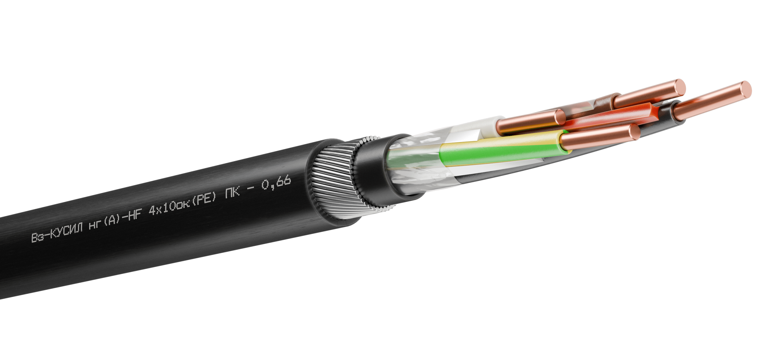
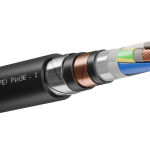
Power cable for use in intrinsically safe circuits
in explosive environments Vz-KUSIL
Fire-resistant cables (with the “FR” index) are designed for use in emergency protection systems (EPS), fire protection networks, as well as for powering equipment that operates during a fire.
Cables can be used in subway facilities.
The main characteristics of the cables are provided in Table 1.
KUSIL cables are manufactured with copper single-wire or multi-wire conductive conductors in accordance with Table 2. The flexibility class of the cable conductors in standard execution is 1 or 2, while in execution with increased flexibility conductors “G” – class 5 according to GOST 22483. Cables with the “l” index are produced with tinned conductors.
The number and nominal cross-section of the conductors are specified in Table 3. By agreement with the customer, cables with a nominal voltage of 0.66 and 1 kV may be manufactured with conductors having a nominal cross-section of up to 6 mm² and up to 61 conductors inclusive, as well as cables with a nominal voltage of 3 kV with conductors having a nominal cross-section of less than 10 mm².
Shape of conductive conductors:
Multi-core cables have all conductors of equal cross-section. Four-core cables with conductors of a nominal cross-section of 25 mm² and larger may have a grounding (PE) or neutral (N) conductor of a smaller cross-section (see Table 4).
In fire-resistant “FR” cables, conductive conductors under the insulation are wrapped with mica-containing tapes, preventing conductor short circuits in case of fire.
The insulation of conductors can be made from materials (see Table 5):
The insulation color of multi-core cables is specified in Table 6. The insulation of single-core cables can be any color. Grounding (PE) conductors have a green-yellow color, and neutral (N) conductors are blue (light blue).
The marking of insulated conductors is either color-coded or numerical – in the form of numbers, with distances between them not exceeding 50 mm.
Each conductor of the cable may have an individual shield:
Insulated or shielded insulated conductors of round multi-core cables are twisted into a core.
The insulated conductors of “Vz” version cables are twisted around a profiled core made of polymer material to ensure longitudinal sealing and impact resistance.
A water-blocking tape is applied over the twisted core of multi-core cables and over the insulation of single-core cables to prevent longitudinal moisture spread in case of damage to the outer sheath.
An extruded separating layer is applied over the tape, filling the free spaces between the conductors. As a result, the cable has a round cross-section, preventing explosive gas mixtures from traveling through the sealed cable from the hazardous area to the safe zone in case of sheath damage. A round-section cable can be used with any type of cable gland.
In fire-resistant “FR” cables without armor, an additional mica-containing tape is applied over the separating layer.
An overall shield can be applied over the separating layer or wrapping in the form of:
The presence of an overall shield is mandatory for unarmored cables with a nominal voltage of 3 kV.
In armored cables with an overall shield, an extruded separating layer is applied over the shield.
Cables may have armor:
The outer sheath of the cables can be made of materials (see Table 5):
The color of the outer sheath is determined upon order (blue, orange, red, etc.); if not specified, cables are manufactured in black.
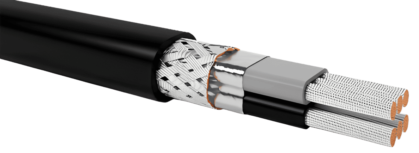
Flexible power cable with flat conductors
KUSIL-G ng(A)-HF 2x10mk(l) PEaEl-P-UF – 0.66
– analog of TFL 492 325/0 cable
| Nominal voltage (U) | AC voltage with a nominal frequency of 50 Hz: 0.66 kV; 1 kV; 3 kV |
| Electrical insulation resistance at t = +20°C, not less than |
|
| Electrical resistance of conductive cores at t = +20°C |
|
| Voltage test with AC at 50 Hz / 10 min |
|
| Operating temperature range (stationary) |
|
| Minimum installation temperature, not below |
|
| Impact resistance at low temperatures |
|
| Climatic performance as per GOST 15150 | Performance “UHL” and “V”, placement categories 1 and 5. Suitable for use in all macroclimatic regions, including the tropics. |
| Fire resistance of cables with the “FR” index |
|
| Longitudinal moisture penetration resistance | Fully blocked within 0.5 m from the penetration point (all cables use a special water-blocking tape). |
| Mold resistance | Cables are resistant to mold fungi, with a biological growth rating of up to 2 points. |
| Minimum bending radii during installation and operation, in Dn (outer cable diameter), not less than |
|
| Permissible pulling force during cable laying, not more than | Not more than 50 N/mm² of conductor cross-section. |
| Service life, not less than |
|
| Warranty period | 5 years from the date of commissioning. |
| Conductor type | Nominal conductor cross-section, mm² | |
| Round | Sector (Segmental) | |
| Single-wire | 1.0 – 50 | – |
| Multi-wire | 1.0 – 1000 | 25 – 400 |
| Number of conductors | Nominal voltage, kV | ||
| 0.66 | 1 | 3 | |
| Nominal conductor cross-section, mm² | |||
| 1 | 1.0 – 50 | 1.5 – 1000 | (10 – 1000) * |
| 2 – 5 | 1.5 – 400 | 10 – 240 | |
| * only for shielded cables | |||
| Conductor designation | Nominal conductor cross-section, mm² | ||||||||||
| Main | 25 | 35 | 50 | 70 | 95 | 120 | 150 | 185 | 240 | 300 | 400 |
| Neutral (N) or grounding (PE) | 16 | 16 | 25 | 35 | 50 | 70 | 70 | 95 | 120 | 150 | 185 |
| Designation of sheath and insulation material | Fire hazard rating | Description of sheath and insulation material, as well as cable type according to the fire hazard rating per GOST 31565 |
| V | – (no index) | cables with PVC plastic insulation and sheath, not propagating fire during single installation |
| ng(A) | cables with PVC plastic insulation and reduced flammability PVC plastic sheath, not propagating fire during group installation of category A | |
| ng(A)-LS | cables with low fire hazard PVC plastic insulation and sheath, not propagating fire during group installation of category A, with reduced smoke and gas emission | |
| ng(A)-LSLTx | cables with low fire hazard PVC plastic insulation and sheath, not propagating fire during group installation of category A, with reduced smoke and gas emission, and low toxicity of combustion products | |
| ng(A)-FRLS | fire-resistant cables with low fire hazard PVC plastic insulation and sheath, not propagating fire during group installation of category A, with reduced smoke and gas emission | |
| ng(A)-FRLSLTx | fire-resistant cables with low fire hazard PVC plastic insulation and sheath, not propagating fire during group installation of category A, with reduced smoke and gas emission, and low toxicity of combustion products | |
| P | ng(A)-HF | cables with halogen-free polymer composite insulation and sheath, not propagating fire during group installation of category A and not emitting corrosive gaseous products during combustion and smoldering |
| ng(A)-FRHF | fire-resistant cables with halogen-free polymer composite insulation and sheath, not propagating fire during group installation of category A and not emitting corrosive gaseous products during combustion and smoldering | |
| Ps | ng(A)-LS | cables with cross-linked polyolefin insulation and low fire hazard PVC plastic sheath, not propagating fire during group installation of category A, with reduced smoke and gas emission |
| ng(A)-FRLS | fire-resistant cables with cross-linked polyolefin insulation and low fire hazard PVC plastic sheath, not propagating fire during group installation of category A, with reduced smoke and gas emission | |
| ng(A)-HF | cables with cross-linked polyolefin insulation and halogen-free polymer composite sheath, not propagating fire during group installation of category A and not emitting corrosive gaseous products during combustion and smoldering | |
| ng(A)-FRHF | fire-resistant cables with cross-linked polyolefin insulation and halogen-free polymer composite sheath, not propagating fire during group installation of category A and not emitting corrosive gaseous products during combustion and smoldering | |
| Rep | ng(A)-LS | cables with ethylene-propylene rubber (EPR) insulation and low fire hazard PVC plastic sheath, not propagating fire during group installation of category A, with reduced smoke and gas emission |
| ng(A)-FRLS | fire-resistant cables with ethylene-propylene rubber (EPR) insulation and low fire hazard PVC plastic sheath, not propagating fire during group installation of category A, with reduced smoke and gas emission | |
| ng(A)-HF | cables with ethylene-propylene rubber (EPR) insulation and halogen-free polymer composite sheath, not propagating fire during group installation of category A and not emitting corrosive gaseous products during combustion and smoldering | |
| ng(A)-FRHF | fire-resistant cables with ethylene-propylene rubber (EPR) insulation and halogen-free polymer composite sheath, not propagating fire during group installation of category A and not emitting corrosive gaseous products during combustion and smoldering | |
| T | ng(A) | cables with thermoplastic elastomer insulation and sheath, not propagating fire during group installation of category A |
| ng(A)-FR | fire-resistant cables with thermoplastic elastomer insulation and sheath, not propagating fire during group installation of category A |
| Number of conductors in the cable | Conductor insulation color | ||||
| Conductor sequence number | |||||
| 1 | 2 | 3 | 4 | 5 | |
| 2 | gray* | blue | – | – | – |
| 3 | gray* | brown | black | – | – |
| gray* | blue | green-yellow | – | – | |
| 4 | gray* | brown | black | blue | – |
| gray* | brown | black | green-yellow** | – | |
| 5 | gray* | brown | black | blue | green-yellow |
| * or natural ** as agreed with the customer | |||||
| Nominal conductor cross-section, mm² | Permissible continuous current loads, A for cables with sheath and insulation material designation “V”, “P”, “T” / “Ps”, “Rep” | Permissible one-second short-circuit currents of cables, kA | ||||||
| Single-core | Multi-core** | Cables with material “V”, “P”, “T” | Cables with material “Ps”, “Rep”, as well as all “FR” cables | |||||
| For direct current | For alternating current* | For alternating current | ||||||
| In air | In soil | In air | In soil | In air | In soil | |||
| 1 | 17 / 20 | 24 / 27 | 14 / 17 | 18 / 20 | 13 / 15 | 16 / 18 | 0,11 | 0,14 |
| 1,5 | 29 / 35 | 41 / 48 | 22 / 28 | 30 / 33 | 21 / 25 | 27 / 31 | 0,17 | 0,21 |
| 2,5 | 37 / 46 | 55 / 63 | 30 / 36 | 39 / 42 | 27 / 34 | 36 / 40 | 0,27 | 0,34 |
| 4 | 50 / 60 | 71 / 82 | 39 / 47 | 50 / 54 | 36 / 45 | 47 / 52 | 0,43 | 0,54 |
| 6 | 63 / 76 | 90 / 102 | 50 / 59 | 62 / 67 | 46 / 56 | 59 / 64 | 0,65 | 0,81 |
| 10 | 86 / 105 | 124 / 136 | 68 / 82 | 83 / 89 | 63 / 78 | 79 / 86 | 1,09 | 1,36 |
| 16 | 113 / 139 | 159 / 175 | 89 / 108 | 107 / 115 | 84 / 104 | 102 / 112 | 1,74 | 2,16 |
| 25 | 153 / 188 | 207 / 228 | 121 / 146 | 137 / 147 | 112 / 141 | 133 / 144 | 2,78 | 3,46 |
| 35 | 187 / 230 | 249 / 274 | 147 / 180 | 163 / 176 | 137 / 172 | 158 / 173 | 3,86 | 4,8 |
| 50 | 227 / 281 | 295 / 325 | 179 / 220 | 194 / 208 | 167 / 209 | 187 / 205 | 5,23 | 6,5 |
| 70 | 286 / 356 | 364 / 399 | 226 / 279 | 237 / 255 | 211 / 265 | 231 / 253 | 7,54 | 9,38 |
| 95 | 354 / 440 | 436 / 478 | 280 / 345 | 285 / 306 | 261 / 327 | 279 / 304 | 10,48 | 13,03 |
| 120 | 413 / 514 | 499 / 546 | 326 / 403 | 324 / 348 | 302 / 381 | 317 / 347 | 13,21 | 16,43 |
| 150 | 473 / 591 | 561 / 614 | 373 / 464 | 364 / 392 | 346 / 437 | 358 / 391 | 16,3 | 20,26 |
| 185 | 547 / 685 | 637 / 695 | 431 / 538 | 442 / 443 | 397 / 504 | 405 / 442 | 20,39 | 25,35 |
| 240 | 655 / 812 | 743 / 821 | 512 / 641 | 477 / 515 | 472 / 598 | 471 / 515 | 26,8 | 33,32 |
| 300 | 760 / 956 | 845 / 924 | 591 / 739 | 539 / 501 | 542 / 688 | 533 / 583 | 33,49 | 41,64 |
| 400 | 894 / 1124 | 971 / 1060 | 685 / 860 | 612 / 661 | 633 / 807 | 611 / 669 | 39,6 | 55,2 |
| 500 | 1054 / 1328 | 1121 / 1223 | 792 / 997 | 690 / 746 | – / – | – / – | 49,5 | 69 |
| 625/630 | 1252 / 1576 | 1299 / 1416 | 910 / 1149 | 774 / 840 | – / – | – / – | 62,37 | 86,95 |
| 800 | 1481 / 1857 | 1502 / 1632 | 1030 / 1302 | 856 / 932 | – / – | – / – | 79,2 | 110,4 |
| 1000 | 1718 / 2163 | 1709 / 1862 | 1143 / 1451 | 933 / 1019 | – / – | – / – | 99 | 138 |
| * Laid in a tightly packed triangular formation ** For four-core and five-core cables, the current load values should be multiplied by a factor of 0.93 | ||||||||
| Insulation Material | Permissible Conductor Heating Temperature, °C | |||
| Continuous permissible | Overload mode | Maximum during short circuit | Non-ignition condition during short circuit | |
| PVC plastic compound; halogen-free polymer composition | 70 | 90 | 160/140* | 350 |
| Cross-linked polyolefin; ethylene-propylene rubber | 90 | 130 | 250 | 400 |
| Thermoplastic elastomer | 125 | 150 | 200 | 350 |
| High heat-resistant thermoplastic elastomer | 200 | 220 | 250 | 350 |
| * For cables with conductors of more than 300 mm² cross-section | ||||
| “Vz” version | |
| No requirements for compliance with GOST R 58342-2019 | |
| Vz- | The cable complies with GOST R 58342-2019 and is intended for use in explosive environments |
| Number of conductors (see Tables 2 and 3) |
| 1…5 – number of conductors in the overall twist, up to 61 conductors by agreement |
| Conductor type (see Table 2) | |
| ok | Single-wire round conductor |
| os | Single-wire sector or segmental conductor |
| mk | Stranded round conductor |
| ms | Stranded sector or segmental conductor |
| Conductor tinning | |
| Untinned conductor | |
| (l) | Tinned conductor |
| Sheath and insulation material (see Table 5) | |
| V | PVC plastic compound |
| P | Halogen-free polymer compositions |
| T | Thermoplastic elastomer |
| Ps | Cross-linked polyolefin insulation, PVC or halogen-free sheath |
| Rep | Ethylene propylene rubber (EPR) insulation, PVC or halogen-free sheath |
| Armor under outer sheath | |
| Non-armored cable | |
| K | Solid layer of galvanized wires |
| B | Steel galvanized tape armor |
| Nominal AC voltage (U), kV |
| 0,66 |
| 1 |
| 3 |
KUSIL
x
–
–
| Conductor flexibility class | |
| Standard flexibility (Class 1 or 2 conductors according to GOST 22483) | |
| -G | Increased flexibility (Class 5, conductors up to 50 mm²) |
| Conductor cross-section, mm² (see Table 2 and 3) |
| 1.0…1000 – nominal conductor cross-section |
| Fire hazard rating (see Table 5) |
| – |
| ng(A) |
| ng(A)-LS |
| ng(A)-LSLTx |
| ng(A)-HF |
| ng(A)-FR |
| ng(A)-FRLS |
| ng(A)-FRLSLTx |
| ng(A)-FRHF |
| Presence of neutral and/or grounding conductor | |
| not required | |
| (N) | neutral conductor |
| (PE) | grounding conductor |
| (N, PE) | neutral and grounding conductor |
| Individual shielding of each conductor | |
| without individual shielding | |
| Em | braid of copper wires |
| El | braid of tinned copper wires |
| Cable with flat conductors (two- and three-core cables) | |
| round-shaped cable | |
| -P | cable with flat conductors (only 0.66 kV and 1 kV, with conductors up to 16 mm²) |
| Overall shielding over all conductors | |
| without overall shielding | |
| E | copper tape wrapping |
| Em | braid of copper wires |
| El | braid of tinned copper wires |
| Ea | alumoflex |
| EaEl | braid of tinned copper wires applied over alumoflex wrapping |
| Special Cable Characteristics | |
| no special characteristic | |
| HL | increased frost resistance (down to -60°C) |
| EHL | resistance to extreme cold conditions (down to -70°C) |
| AHL | resistance to Antarctic cold climate (down to -90°C) |
| UF | resistance to solar radiation, exposure to rain, dynamic abrasive dust impact, and frost formation |
| M | oil and fuel resistance* |
| H | resistance to chemically aggressive environments |
| T | heat resistance up to +200°C (only for material “T”) |
| ZG | sheath resistance to damage by rodents, ants, and termites. Fire hazard indicator “ng(C)-HF” or “ng(C)-FRHF” |
| s | outer sheath in blue color |
Note:
* Four-core cables with conductors of 25 mm² or more may have one PE or N conductor of a smaller cross-section (see Table 4). In the designation of these cables, a plus sign is used to add the number and nominal cross-section of the grounding conductor. For example: KUSIL ng(A) 3x120ms + 1x70ms(N) VB-1
| Examples of Cable Designation in Orders | |
| KUSIL ng(A)-LS 3×2.5ok V-HL–0.66 TU 3500-013-76960731-2008 | Flame-retardant, with low smoke and gas emission, with insulation and sheath made of PVC compounds with reduced fire hazard, with three single-wire round conductors of nominal cross-section 2.5 mm², round cable in cross-section, with extruded filling between conductors, for nominal voltage of 0.66 kV, operating temperature from -60º to +50ºC, installation down to -30ºC. |
| Vz-KUSIL ng(A)-HF 5x95ms(PE) PEl–1 TU 3500-013-76960731-2008 | Cable for use in explosive environments, compliant with GOST R 58342-2019, flame-retardant, with insulation and sheath made of halogen-free polymer compositions, with an overall screen in the form of a braid of tinned copper wires, with five multi-wire sector-shaped copper conductors of nominal cross-section 95 mm², one of the conductors being a grounding (PE) conductor, round cable in cross-section, with extruded filling between conductors, for nominal voltage of 1 kV, operating temperature from -50º to +50ºC, installation down to -15ºC. |
0 шт.
цена за шт. - 0 ₽

Error: Contact form not found.
Error: Contact form not found.


