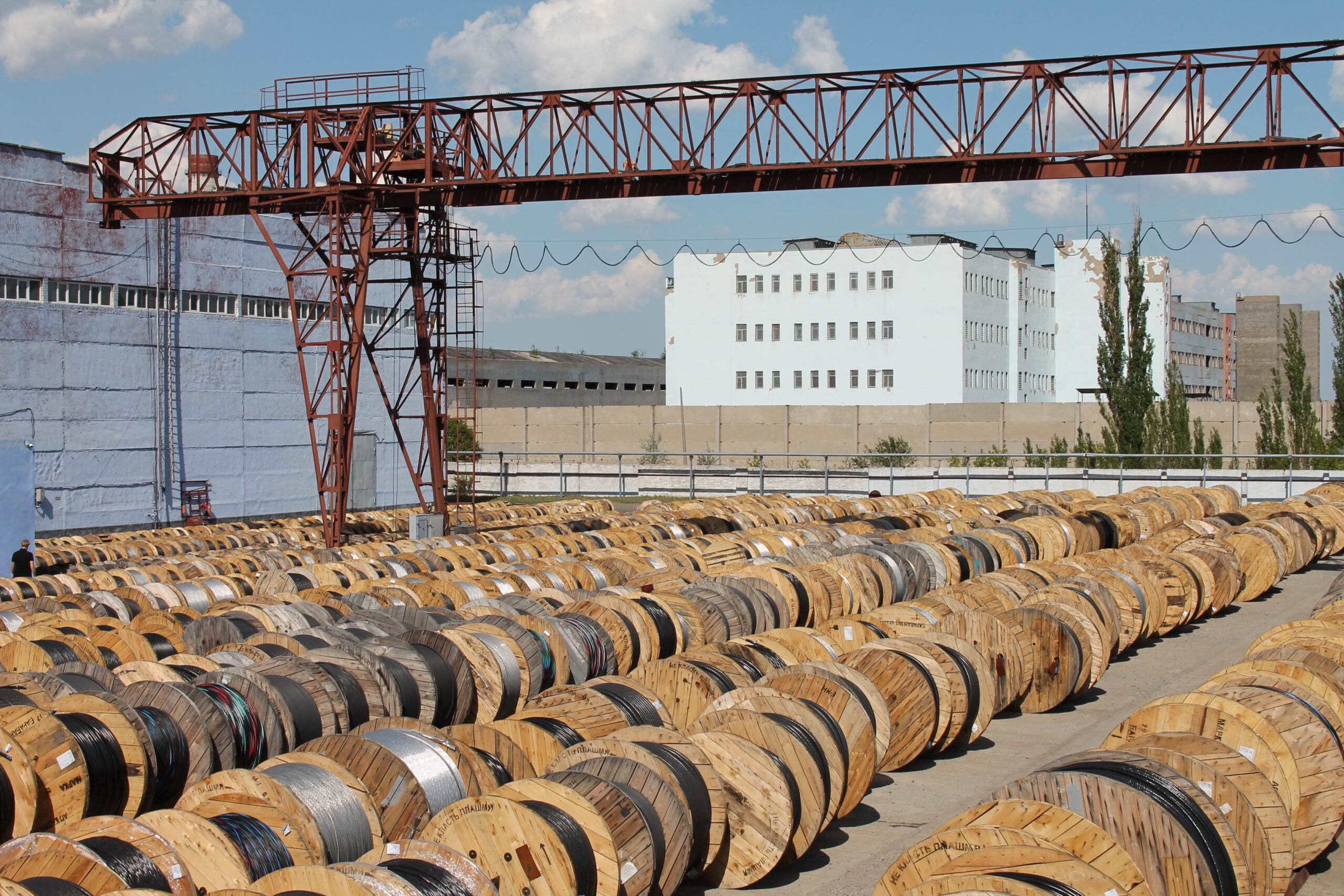
Why a coil is exactly 305 meters
The standard length of a UTP cable coil is 305 meters. This value is not accidental: 305 meters equals 1000 feet. The American system of measures, in which the first structured cabling standards were developed, defined this length as the basic unit of supply. In the metric system, it turned out to be a “non-round” number that has become established in manufacturers’ catalogues worldwide.
The 305-meter length is optimal for two reasons. First, it is a multiple of the maximum length of horizontal cable in a structured cabling system: 90 meters for a permanent link. One coil allows several independent lines to be laid, taking into account the reserve. Second, a coil of this weight and dimensions is convenient for transportation and installation. Shorter coils produce a lot of waste on end sections; longer ones are difficult to move. More about the construction and characteristics of twisted pair — in the material UTP communication cable: complete guide.
Cable is supplied in 305-meter coils regardless of category: Cat5e, Cat6, shielded or unshielded. For outdoor installation, cable with a polyethylene sheath or UV protection is used: UTP or FTP: which twisted pair cable to choose.
Formula for calculating cable consumption
Cable consumption per line consists of the route length and the installation reserve. The route length is the distance from the point where the switching equipment is installed (patch panel, cabinet) to the outlet at the workplace, measured along the actual cable route, taking into account rises, drops and detours.
Consumption per line = route length + installation reserve
Number of lines = 305 m / average consumption per line
The installation reserve is the additional length that compensates for technological operations and possible errors. The reserve must not be confused with the termination reserve: these are two different quantities. The termination reserve (0.3 m per outlet and 0.3 m per patch panel according to GOST R 53246-2008) is already included in the total installation reserve. The technological reserve for turns, laying and possible rework is usually taken as 10% of the route length.
The final consumption formula for one line: consumption = route length × 1.1 + 0.6 m. The coefficient 1.1 is a 10% technological reserve, 0.6 m is the termination reserve on both sides (0.3 m each for the outlet and patch panel). This is a practical guideline, not a normative percentage: the actual reserve depends on the complexity of the route, the number of turns and the installer’s experience.
If the line is laid along walls with many turns, the reserve may be increased to 15% or 20%. For straight routes in cable duct, 10% is sufficient. The maximum length of a permanent link is 90 meters, so when calculating it is important to ensure that the route length does not exceed this value: UTP cable installation: installation norms.
What reserve to allow for installation
The installation reserve takes into account several operations:
- Laying the route. The cable must be laid with a slight slack at turns to avoid tension. For each turn of the route, 0.2–0.3 m is added. With 4–5 turns, this gives up to 1.5 m per line.
- Entry into the cabinet. The cable is routed into the cabinet, laid in cable organizers and terminated on the patch panel. The entry reserve is at least 1 m.
- Outlet. The cable is brought to the mounting box, stripped and connected to the keystone module or outlet. The termination reserve is 0.3 m.
- Rework. If a connector is crimped incorrectly, the end is cut off and crimped again. Each rework requires 0.1–0.2 m. Practice shows that one or two reworks are sufficient for 10 lines.
The total practical reserve for lines in cable duct is 10% of the route length plus 0.6 m for termination. For lines in corrugated conduit or with many turns, the reserve is increased to 15%. This is not a normative requirement, but engineering practice confirmed by calculation methods: a 10% technological reserve is used in training and design calculations.
Calculation examples for different lines
Example 1. Line of 15 meters.
Route length: 15 m. Reserve 10%: 1.5 m. Termination reserve: 0.6 m. Consumption: 15 + 1.5 + 0.6 = 17.1 m. From a 305 m coil: 305 / 17.1 ≈ 17.8. Round down — 17 lines.
Example 2. Line of 25 meters.
Route length: 25 m. Reserve 10%: 2.5 m. Termination reserve: 0.6 m. Consumption: 25 + 2.5 + 0.6 = 28.1 m. From a 305 m coil: 305 / 28.1 ≈ 10.8. Round down — 10 lines.
Example 3. Line of 40 meters.
Route length: 40 m. Reserve 10%: 4 m. Termination reserve: 0.6 m. Consumption: 40 + 4 + 0.6 = 44.6 m. From a 305 m coil: 305 / 44.6 ≈ 6.8. Round down — 6 lines. Important: 40 m is less than 90 m, so the line meets the permanent link limit.
Example 4. Mixed facility.
Office: 8 lines of 20 m and 4 lines of 35 m. Consumption for short lines: 8 × (20 × 1.1 + 0.6) = 8 × 22.6 = 180.8 m. Consumption for long lines: 4 × (35 × 1.1 + 0.6) = 4 × 39.1 = 156.4 m. Total consumption: 337.2 m. One 305 m coil is not enough. Two coils will be required, or the project must be adjusted: reducing route lengths or the number of lines.
Table: how many lines from a 305 m coil
The calculation was performed using the formula: consumption = route length × 1.1 + 0.6 m. The 10% reserve is a practical guideline, not a norm. The actual reserve depends on the project.
| Average line length | Consumption with 10% reserve + 0.6 m | Approximate lines from 305 m |
| 10 m | 11.6 m | 26 |
| 15 m | 17.1 m | 17 |
| 20 m | 22.6 m | 13 |
| 25 m | 28.1 m | 10 |
| 30 m | 33.6 m | 9 |
| 40 m | 44.6 m | 6 |
| 50 m | 55.6 m | 5 |
| 60 m | 66.6 m | 4 |
| 70 m | 77.6 m | 3 |
| 80 m | 88.6 m | 3 |
| 90 m | 99.6 m | 3 |
With a route length of 90 m, the consumption with reserve is 99.6 m. From a 305 m coil, 3 lines are obtained with a remainder of 6.2 m. The remainder can be used for a short line or patch cord.
Ethernet line length limitations
Cable route length and Ethernet channel length are not the same thing. The ANSI/TIA-568 and ISO/IEC 11801 standards establish limitations: the maximum length of a permanent link is 90 meters, the maximum channel length is 100 meters. The 10-meter difference is the patch cords at both ends of the line: one in the patch cabinet, the second at the workplace. The total length of patch cords must not exceed 10 meters.
When calculating cable consumption from a coil, only the permanent link is taken into account — the cable that is laid in the wall, tray or cable duct. Patch cords are purchased separately; their length is not included in the coil calculation. If the route length from the cabinet to the outlet exceeds 90 meters, the line will not comply with the standard, and either the switching node must be moved closer to the workplaces or fibre optic cable must be used. More about choosing a category — in the article UTP Cat5e or Cat6: which to choose.
Typical calculation mistakes
Counting only the distance between points. The direct distance from the cabinet to the outlet on the plan does not take into account the actual laying path: rises to the ceiling, drops to the outlet, detours around obstacles. The actual route length is always greater than the straight-line distance.
Forgetting the reserve at the outlet and cabinet. Each line requires at least 0.6 m additionally: 0.3 m for termination at the outlet and 0.3 m for the patch panel. Without this reserve, the cable may not reach the connection point.
Not taking vertical sections into account. When laying between floors, the cable runs through a riser. A floor height of 3 m adds 3–4 m per line. If this is not taken into account, the coil will not be enough.
Assuming all lines are the same. In a real facility, lines have different lengths: from 10 to 80 meters. Calculation by average length gives an approximate result. For an accurate calculation, sum the consumption of each line separately.
Buying a coil “just enough”. If the calculation shows that exactly 10 lines come from a coil, and 10 are needed, it is better to purchase two coils or add one line with a reserve. The remainder from a coil will always be useful for patch cords or repairs.
Ignoring the 90-meter limit. If the route exceeds 90 meters, the line will not pass standard testing. Increasing the reserve will not solve the problem — the laying scheme will need to be changed.
FAQ
How many lines can be obtained from a 305-meter coil?
The number of lines depends on the average route length. At a length of 15 m — about 17 lines, at 25 m — 10 lines, at 40 m — 6 lines, at 60 m — 4 lines. The exact calculation is performed using the formula: consumption = route length × 1.1 + 0.6 m, then 305 is divided by the average consumption.
Why is a coil exactly 305 meters long?
305 meters equals 1000 feet. Structured cabling standards were developed in the USA, where the imperial system of measures is used. The 305 m length has become established as the standard for twisted pair supply worldwide.
What reserve should be allowed for installation?
The practical guideline is 10% of the route length plus 0.6 m for termination on both sides. For routes with many turns, the reserve is increased to 15%. This is not a normative percentage, but engineering practice. The actual reserve depends on the complexity of the project.
Can two lines be joined if the cable length is insufficient?
No. Joining two lengths of twisted pair with a twist or terminal block disrupts the characteristic impedance and leads to signal loss. The line will not comply with the standard. If the cable is insufficient, the route is re-laid using a longer length from a new coil.
Is the length of patch cords included in the coil calculation?
No. Only the permanent link is laid from the coil — the cable in the wall, tray or cable duct. Patch cords are purchased separately. The total length of patch cords at both ends of the line must not exceed 10 meters so that the total channel length remains within 100 meters.
Sources
- ANSI/TIA-568.2-D «Balanced Twisted-Pair Telecommunications Cabling and Components Standard» — in force — TIA TR-42 committee — permanent link (90 m) and channel (100 m) length limitations.
- ISO/IEC 11801-1 «Information technology — Generic cabling for customer premises» — in force — International Organization for Standardization — channel and permanent link length limitations.
- GOST R 53246-2008 «Information technologies. Structured cabling systems. Design of main system nodes. General requirements» — in force — cable termination reserve: 0.3 m for twisted pair at the workplace and 3 m for optical cable.
- Leviton. «Application Note: Three Cabling Subsystems» — technical guide — leviton.com — permanent link 90 m, channel 100 m.
- Fluke Networks. «Differences Between Wiring Codes T568A vs T568B» — technical article — flukenetworks.com — pinout standards.
- KazKabel. «UTP communication cable: complete guide» — practical guide — kazkabel.kz — construction and characteristics of twisted pair.
- KazKabel. «UTP cable installation: installation norms inside, outside, in the ground and on a messenger wire» — practical guide — kazkabel.kz — laying rules, length limitations.
- KazKabel. «UTP Cat5e or Cat6: which to choose» — technical article — kazkabel.kz — category differences, length limitations for 10 Gbit/s.
- KazKabel. «UTP or FTP: which twisted pair cable to choose» — technical article — kazkabel.kz — choice of shielded and unshielded cable.