
Connection of Power Cables: Joints, Installation and PUE Regulations
Connection of power cables is one of the key operations in the construction, repair and reconstruction of electrical networks. Since the construction length of a cable is limited by production technology and ease of transportation, when laying long lines it becomes necessary to create reliable and long‑term connections between individual sections. In addition, it is required to connect the cable to electrical equipment (transformers, switchgear, incoming panels) or to transition from an underground line to an overhead line.
The quality of these operations directly affects the reliability of power supply, electrical safety and the service life of the cable line. This guide covers the main types of joints for power cables, their design features, selection criteria and installation technology in accordance with the requirements of the Electrical Installation Regulations (PUE) and GOST standards. It is important to first properly perform power cable laying — this ensures correct route geometry and facilitates subsequent joint installation.
1. Main tasks of cable accessories
Connecting and terminating cables and branching them are carried out using special devices — cable joints. Depending on the purpose, several types of such products are distinguished.
- Straight joints — used to connect power cables to each other into a single line. They provide electrical contact of the conductors, restore insulation and seal the joint. Such joints usually remain underground or in cable structures after installation.
- Terminations for power cables — designed for terminating a cable with a joint and connecting it to live parts of equipment (busbars, transformer bushings, distribution panels). They also seal the cable end and protect against moisture ingress.
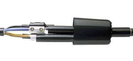
- Branch joints — used to create branches from the main line to additional consumers without cutting the main cable.
- Transition joints — used to connect cables with different types of insulation (for example, paper‑impregnated and plastic) or with a different number of cores.
- Stop joints — used on cables with paper‑impregnated insulation on routes with large elevation differences to prevent the impregnating compound from flowing down.
2. Construction and main elements of joints
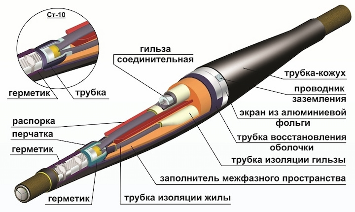
Regardless of the type, any power cable joint is a set of materials and parts that provide:
- Reliable electrical contact between the connected conductors;
- Restoration of insulation matching the voltage class of the cable;
- Sealing of the connection point, protection against moisture, chemically active substances and mechanical damage;
- Equalization of the electric field at the ends of the screens (for medium voltage cables).
A kit for connecting a power cable usually includes:
- Connectors or ferrules for joining conductors (copper or aluminium, with bolts or for crimping);
- Insulating elements (tapes, tubes, gloves made of PVC, cross‑linked polyethylene or heat‑shrinkable materials);
- Shielding and stress‑control elements (for 6–35 kV cables);
- Metal or polymer housing for mechanical protection and sealing (for straight joints);
- Earth conductors and links for connecting metal sheaths and armour.
3. Classification by material
The modern market offers joints for power cables for voltages up to 35 kV, made of various materials. The choice of a specific type depends on operating conditions, installer qualifications and project requirements.
| Joint type | Design features | Advantages and disadvantages |
|---|---|---|
| Heat‑shrinkable | Made of polymer materials (thermoplastics) that have undergone radiation treatment. When heated (with a torch or hot air gun), the joint tightly compresses the cable, forming a sealed connection. | — High sealing and mechanical strength; — Resistance to chemicals and UV radiation; — Wide operating temperature range; — Simple and fast installation. |
| Cold‑shrink joints | Made of elastomers pre‑stretched on a plastic support. After removing the support, the joint shrinks and fits the cable without heating. | — No heat source required (safe in hazardous areas); — Uniform and constant compressive pressure; — Convenient for installation in confined spaces. |
| Resin (epoxy) joints | The cavity of the joint is filled with a special epoxy‑based compound that cures and forms a monolithic insulation. | — High mechanical strength; — Resistant to vibration and aggressive environments; — Labour‑intensive installation, long curing time. |
| Cast iron joints | Consist of two halves bolted together and filled with bituminous compound. Previously widely used for paper‑insulated cables. | — High mechanical strength, reliable impact protection; — Bulky, heavy, require skilled installation; — Rarely used in modern networks. |
| Lead joints | Hermetic metal joints that are soldered to the lead sheath of the cable. | — Complete sealing, compatible with paper‑impregnated insulation; — Complexity of soldering, high labour intensity. |
4. Selection of joint based on operating conditions
Proper selection of accessories is the key to longevity of the cable line. The following factors must be considered when choosing.
| Criterion | Recommendations |
|---|---|
| Rated voltage and conductor cross‑section | A joint for a 10 kV power cable or another voltage class must strictly match the cable parameters. The joint marking indicates the conductor cross‑section for which it is designed (e.g., 3×70‑120). |
| Cable insulation type | Different types of joints are used for cables with paper‑impregnated, plastic (PVC, XLPE) or rubber insulation. Transition joints are used to connect different cable types. Special joints are available for XLPE‑insulated cables, taking into account the characteristics of this material. More about cable types can be found in the overview article about power cables. |
| Environmental conditions | For laying in the ground, damp basements, outdoors or inside dry rooms, joints with the appropriate degree of protection (IP) are required. Terminations may be intended for outdoor (KN) or indoor (KV) installation. It is also important to observe the standardised distances between power cables in a trench or tray to ensure normal thermal conditions and access for joint maintenance. |
| Presence of armour and screen | When terminating cable conductors with armour and a metal sheath, their reliable earthing through the joint must be provided. |
| Expected mechanical loads | On routes with a high probability of damage (construction sites, heaving soils), joints with a strong metal housing are preferable. |
5. Installation technology for power cable joints
Installing joints on a power cable is a critical operation that requires strict compliance with the manufacturer’s instructions and safety rules. The general installation technology for power cable joints includes the following steps.
- Cable preparation: The cable is stripped of outer coverings, armour and sheath to a length specified in the joint instruction. Insulation is removed from the conductor ends. When preparing a cable with plastic insulation, care must be taken not to damage the current‑carrying conductors. Before starting work, ensure that the cable has been laid in compliance with all regulations — the article “Power cable laying” can help with this.
- Connecting the conductors: The conductors are connected using ferrules (by crimping) or bolted connectors. For aluminium conductors, the oxide film must be removed before crimping and the contact filled with quartz‑vaseline paste. For plastic‑insulated cables, bolted shear‑head connectors that provide a standardised clamping force are often used.
- Restoring the insulation: Insulating tapes are applied to the connection point or heat‑shrinkable tubes are slipped on and then heated. For medium voltage cables, shielding elements are placed over the insulation to equalise the electric field.
- Connecting screens and armour: Metal screens and armour are connected to each other using a copper link and earthed. The cross‑section of the earthing conductor must comply with the PUE requirements. The metal housing of the joint (if provided) is also earthed.
- Sealing and protection: An outer housing (for straight joints) or a heat‑shrinkable glove and end terminals (for terminations) are placed over the assembled structure. The joint cavity is filled with a hydrophobic compound (for resin joints) or sealed using heat‑shrinkable tubes with an internal adhesive layer.
6. Terminating power cables
Connecting and terminating cables in switchgear and at equipment inlets is carried out using terminations. Terminating a cable with a joint includes cable preparation, fitting terminals (copper or aluminium) onto the conductors and installing insulating materials (heat‑shrinkable gloves, tubes).
For terminating cables in dry rooms at voltages up to 1 kV, simplified seals without joints (for example, insulation with tapes and filling with compound in a cup) may be used. However, this method does not provide adequate sealing and reliability. Professional termination of cable conductors and of the cable as a whole is performed only using certified accessories.
Insulation of a power cable connection must withstand the test voltages specified for that cable line and comply with GOST requirements. Clause 2.3.65 of the PUE states that joints for power cables must be used in accordance with current technical documentation and ensure protection against moisture ingress and other harmful substances.
7. Regulatory requirements
All work on connecting and terminating cable lines is regulated by the following documents.
- GOST 13781.0-86 “Joints for power cables for voltages up to 35 kV inclusive. General specifications” — sets basic requirements for design, marking and test methods.
- PUE, Chapter 2.3 “Cable lines with voltage up to 220 kV” — contains requirements for joint installation, earthing of sheaths and corrosion protection. In addition, the PUE specifies the distances between power cables that must be maintained when laying several lines to avoid overheating and to provide access to the joints.
- GOST R 53315-2009 “Cable products. Fire safety requirements” — defines the requirements for joint materials in terms of fire safety.
- Manufacturers’ instructions — contain step‑by‑step descriptions of installation for specific joint types and must be strictly followed.
The reliability and durability of a cable line directly depend on compliance with these standards. GOST‑compliant power cable joints guarantee that the product has passed the necessary tests and meets safety requirements.
8. Conclusion
Proper execution of power cable connections using quality materials and strict adherence to the technical procedures is the key to long‑term and trouble‑free operation of an electrical network. Understanding the types of joints, their design features and installation rules is necessary for both designers and electricians.
When choosing cable products, attention should be paid to their compliance with GOST requirements and operating conditions. View the wide range of power cables, as well as VVGng‑A‑LS power cable and copper conductor power cable from the leading manufacturer JSC “Kazenergocable” in the relevant sections of the website. Additional technical materials on the installation and design of cable lines are available in our blog.


